Using DimXpert

Use a suite of DimXpert tools to insert dimensions and tolerances manually or automatically.

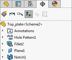
The DimXpertManager:

  • Lists the tolerance features defined by the DimXpert by feature.
  • Displays DimXpert tools.


To change the tree display, right-click the part name in the DimXpertManager, select Tree Display, and select a display option.

To use DimXpert for parts:

  1. Open a part to dimension using DimXpert.
  2. Set the DimXpert options. Click Tools > Options > Document Properties, and set the various DimXpert options, such as Geometric Tolerance.
  3. Insert dimensions and geometric tolerances manually or automatically.
    Option Description
    To manually insert dimensions and geometric tolerances:
    1. Set the datums using the Datum tool.
    2. Add tolerances and dimensions using the DimXpert tools, such as Size Dimension , Location Dimension , Pattern Feature , and Geometric Tolerance .
      Use the feature selector to define the feature types.
    3. Click Show Tolerance Status to see which features are under or over constrained for size and location.
    4. Apply additional dimensions and tolerances as needed to fully constrain the part.
      To set the color of DimXpert dimensions, click Options Tool_Options_Standard.gif > System Options > Colors. Under Color scheme settings, select Annotations > DimXpert.
    To automatically insert dimensions and geometric tolerances:
    1. Click Auto Dimension Scheme (DimXpert toolbar) or Tools > DimXpert > Auto Dimension Scheme.
    2. Set the PropertyManager options.
    3. Click .
  4. Save the part.

Multiple Edge Selection

You can create dimensions between two planes by selecting two edges when the corresponding planes are parallel.


Use of Reference Geometry with DimXpert Dimensions

You can create DimXpert dimensions using reference planes, axes, points, and center of mass symbols.