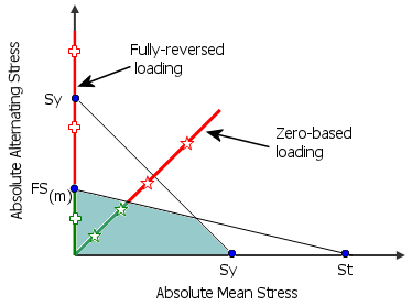
The blue and red regions of the fatigue check plot are determined from
the diagram below. For each node, the program calculates the alternating and mean stresses based
on the defined fatigue event type.

FS(m) = Modified material fatigue strength, Sy = Material yield stress, St = Material tensile strength
-
For a zero-based loading fatigue
event
 , all points are
located on the 450 axis with coordinates:
mean stress = alternating stress = ½ * max [P1
or (P1-P3)/2)]
where P1, P2, P3 are the first, second, and third principal stresses,
respectively.
Regions of the model with corresponding points in the green region of the
diagram are blue in the fatigue check plot, and are safe from fatigue loading. Regions of
the model with points outside the green region are red in the fatigue check plot, and are
susceptible to failure due to fatigue.
-
For a fully-reversed loading fatigue
event
 , all points are
located on the vertical axis (mean stress =0) with alternating stress = max [P1 or (P1-P3)/2)].
Regions of the model with alternating stress smaller than the modified
material fatigue strength FS(M) are blue in the fatigue check
plot, and are safe from fatigue loading. Regions of the model with alternating stress
larger than FS(M) are red in the fatigue check plot, and are
susceptible to failure due to fatigue.
Click Back to return to the previous topic.