You set the folder for storing analysis data.
To display the dialog box, click . On the Default Options tab,
click Results.
Default solver
Sets the default solver, Automatic, Direct sparse, or
FFEPlus.
The Automatic option for
the solver selection is applied to Static, Frequency, Buckling, and Thermal studies.
Results folder
| SOLIDWORKS document folder |
Sets the results folder in the
same directory of the model folder.
|
Under sub folder
|
Sets a sub-folder of the model folder as
the destination folder of the analysis results.
|
|
| User
defined |
Specify the location of the
results folder of new studies. To change the default location, click
Browse (...) and select a different
directory.
|
Keep temporary database files
|
If checked, the software saves temporary
analysis files.
|
|
In the course of solving a problem, the software creates temporary files.
For large problems, these files can be large. To save disk space, the software
deletes all temporary files on completing the solution. If this check box is
selected, the software will save all temporary files.
Report folder
Specify the location of the report for new studies. To change this
default, click Browse (...) and select a different directory.
| Results
folder |
If selected, the study report is
saved in the same location as the results folder. |
| User
defined |
Specify the location of the report
folder for new studies. To change the default location, click
Browse (...) and select a different
folder. |
Trend Tracker
| Backup
models for Restore to Iteration |
Select to save backup copies of
parts and assemblies when you add an iteration using Trend Tracker.
When this option is cleared, the software adds information to the
gallery, Trend Journal, and graphs, but does not save a backup file.
|
| User
defined |
Specify the location of the report
folder for new studies. To change the default location, click
Browse (...) and select a different
folder. |
Additional options
| Show
bodies which are excluded from analysis |
Select to include the geometry of bodies excluded from
simulation in the results plots. To exclude a
body from analysis, right-click its icon in the Simulation study
tree and select Exclude from
Analysis. The excluded body will be
hidden.
|
Intermediate Results (Nonlinear Analysis only)
| Show intermediate
result up to the current iteration (while running the nonlinear
study) |
Select to visualize updated (up to the current
iteration) result plots while running a nonlinear study.
When the first iteration step completes, the results for the
active plot are shown on the graphics area. As the solution
progresses to the next iteration step, the active plot gets
dynamically updated.
By getting visual feedback of the results as the solution
progresses, you can make decisions to either stop the simulation
and make adjustments to the input, or let the solver proceed
with the current settings.
- If you have not activated a result
plot, the first plot under Results is dynamically
updated in the graphics area.
-
To toggle the visibility between
the plots under Results, right-click the active plot
and click Show or Hide.
- For a new Simulation study, first
you need to define the default result plots in
.
|
Average stresses at mid-nodes (high-quality solid
mesh only)
Select this option to get better stress results when irregular
high stresses occur at mid-side nodes of high-quality solid elements that are located at
areas with steep curvatures.
For a high-quality solid element,
the stresses at the mid-side nodes are calculated by averaging the stress values of the
nearest corner nodes. This stress averaging method improves the calculation of stresses
at mid-side notes for tetrahedral elements located at areas with steep curvatures. An
example of the stress-averaging scheme is shown.
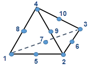 |
- Stresses at corner nodes (1, 2, 3, and 4)
globally averaged over the shared elements.
- Stresses at mid-side nodes (5, 6, 7, 8, 9,
and 10) averaged over the nearest corner nodes. For example,
stress (node 5) = (stress (node 1) + stress (node 2)) /
2
|
The stress-averaging algorithm at mid-side nodes is available for all
stress-based results across all studies, except for Linear Dynamic studies.
The
improved stress averaging algorithm does not modify the stress results calculated at the
corner nodes of tetrahedral elements.