Certain types of models are better suited to design automation than others. When setting up models for automation, consider how they fit into an assembly and how the parts might change when automated.
Example 1
This illustration shows a simple support that uses planes.
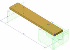
Several planes have been created so that the sketches and features can be referenced to them (coincident, up to surface, etc.) This allows the dimension for the plane to be changed and the extrusion extended with it. When placed in an assembly, other components can be mated to this plane so that they move with consideration to the parts altered.
Using a coincident mate with the face could cause problems with more complex parts.
Example 2
This fitting also uses planes. If DriveWorksXpress is suppressing or unsuppressing the flange feature, the face of the flange face used in the mate would no longer be there.
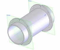
Planes have little effect on the part or assembly file size but do increase the stability of the part during part configuration. Stability becomes increasingly important as part complexity increases. This principle also applies to axes, although not ‘temporary axes’, which disappear if the geometry disappears.