Design Study with Composite Shells

When working with composite materials, you may want to design the optimal layup for a specific application to minimize expenses. For example, you might want to find the optimal thicknesses and ply orientations of a composite hull that result in minimal deflection. In general, layup optimization of composites can be time consuming because you can define several variables with different combinations of ply thicknesses and ply orientations.

You can define a Design Study for a study with composite shells. You then define the ply angles and ply thicknesses as the variables to optimize or evaluate. In addition, you can define the material property values as the variables if all plies are the same material.
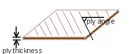
For example, if you model a carbon fiber reinforced epoxy composite, you can define the material properties, ply angles, and ply thicknesses as the variables. If you model a sandwich shell with glass reinforced epoxy as the skins and wood as the core, you can only define the ply angles and thicknesses as the variables.

Defining Ply Angle as a Parameter

You can define the ply orientation of each ply as a parameter. You can then use it as a variable in the Design Study.

  1. In the Simulation study tree, under the Parts folder, right-click a shell and select Edit Definition.
  2. In the PropertyManager, under Type, select Composite.
  3. Under Composite Options, in the Composite shell plies table, right-click the cell for Angle of a ply and select Link Values.
  4. In the Parameters dialog box, click Edit/define.
  5. In the next Parameters dialog box that appears, click Add.
  6. In the Add Parameters dialog box:
    1. For Filter, select Mesh.
    2. For Type, select Ply angle.
  7. For User defined value, enter a value for ply angle.
    You can change this value from a Design Study after you add the parameter as a variable.
  8. Click OK.
  9. In the Parameters dialog box, click OK.
  10. In the next Parameters dialog box, select the newly defined parameter and click OK.
  11. In the Shell Definition PropertyManager, click .
    The program defines the ply angle of the selected ply as a parameter.

Defining Ply Thickness as a Parameter

You can define the thickness of each ply as a parameter. You can then use it as a variable in the Design Study.

  1. In the Simulation study tree, under the Parts folder, right-click a shell and select Edit Definition.
  2. In the PropertyManager, under Type, select Composite.
  3. Under Composite Options, in the Composite shell plies table, under Thickness, right click the cell for a ply and select Link Values.
  4. In the Parameters dialog box, click Edit/define.
  5. In the next Parameters dialog box that appears, click Add.
  6. In the Add Parameters dialog box:
    1. For Filter, select Mesh.
    2. For Type, select Length/Displacement/Ply thickness.
  7. For User defined value, enter a value for ply thickness.
    You can change this value from a Design Study after you add the parameter as a variable.
  8. Click OK.
  9. In the Parameters dialog box, click OK.
  10. In the next Parameters dialog box, select the newly defined parameter and click OK.
  11. In the Shell Definition PropertyManager, click .
    The program defines the ply thickness of the selected ply as a parameter.