SOLIDWORKS Simulation represents internally a pin connector as a beam with a specified
axial or rotational stiffness. Each end node of the beam is located at the centroid of the
connected cylindrical face (or shell edge).
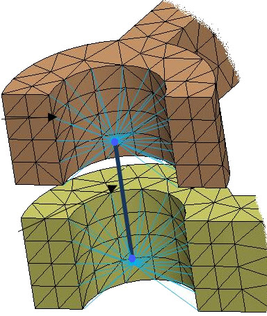
For a rigid connection type, rigid bar elements connect the beam end nodes to
the cylindrical face nodes. All faces connected to the pin remain coaxial under loading, and
maintain their original shape. These cylindrical faces can move as rigid bodies relative to
each other depending on the axial and rotational stiffness characteristics of the pin
connector. Because of the introduction of rigid regions, you may observe stress hot spot areas
near the pin connector. Stress hot spots decrease gradually with distance, until they
disappear in regions about one diameter away from the cylindrical faces.
For linear static studies only, you can select a distributed coupling
formulation for pin connectors. Distributing coupling constrains the motion of the nodes of
the attached cylindrical faces (coupling nodes) to the translation and rotation of the beam
end node (reference node) in an average sense. A distributed connection allows the coupling
nodes of a cylindrical face to move relative to each other. The distributed connection type
produces more realistic stress and displacement fields at the vicinity of pin connectors.
A pin's axial stiffness defines the relative axial movement between the
cylindrical faces (or circular edges) connected to a pin. A pin's rotational stiffness defines
the relative rotational movement between the cylindrical faces (or circular edges). For a pin
connecting more than two cylindrical faces or edges, the software redistributes the axial and
rotational stiffnesses based on each pin segment's geometric characteristics (such as
sectional area, polar moment of inertia, and length). A pin segment connects two consecutive
cylindrical faces and has two end joints. Each pin joint is located at the centroid of the
connected cylindrical face or circular edge.
Listing of Pin Connector Forces
The solver calculates the
connector forces at the two end joints of each pin segment.
For example, for a single pin definition connecting four cylinders of a
hinged plate, as shown below, the solver calculates and lists the pin forces at four pin
joints. Each pin joint is located at the centroid of each cylindrical face connected to a pin.
The software lists four forces per connector joint with respect to the pin's local
coordinate system. An image of a pin's cross section with the forces calculated at a joint is
shown.
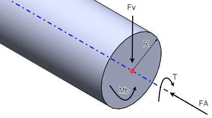
- FA = axial force across the pin's cross
section
A positive axial force indicates that the pin segment is under
tension; a negative axial force indicates compression. The software reports the loads
acting on a pin segment as pin connector loads at the pin joints. No balance of loads
for the pin segment is considered for the listing of connector loads at the
joints.
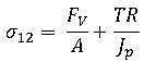
- FV = shear force across the pin's cross
section
- Mb = bending moment
- T = Torque
For pin joints that are common to consecutive pin segments, for example joint 2 in the
figure below, the solver calculates two sets of pin connector forces for the left and right
side of the common joint. The image illustrates a cross section of a pin connector with two
pin segments (blue color) attached to three cylindrical faces..
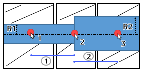
The radius of a pin
connector, R, is the radius of the cylindrical face or circular edge attached to the pin.
Pin segments of a single pin connector definition can have different radiuses.
The solver calculates the von Mises stresses for the left and right side of
the common joint. The software compares the von Mises stresses, and lists the set of pin
forces (from the left or side side) that yield the highest von Mises stress.
The von Mises stress for a general plane stress case is given by:
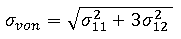
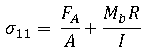 ,
,  ,
,  ,
, 
For the pass/no pass
safety check of a pin connector, the software selects the pin joint with the maximum
combined loads based on the von misses stress criterion to evaluate the factor of safety of
the pin. See topicSOLIDWORKS Simulation Help: Pin Connector - Safety
Check