Specify the following properties when you create a geometric tolerance symbol.
To specify geometric tolerance properties, do one of the following:
- For parts, click Geometric Tolerance
 (MBD Dimension toolbar) or .
- For drawings, click Geometric Tolerance
 (Annotation toolbar) or
.
Height
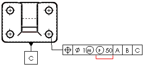
If you click Projected Tolerance
 , enter a projected tolerance
zone (PTZ) in Height.
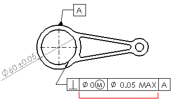
Tolerances
Type tolerance values for Tolerance 1 and Tolerance 2.
Unit Basis Tolerance
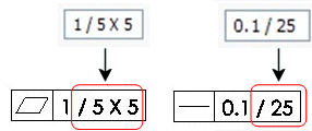
You can apply flatness and straightness tolerances on a unit basis. You apply a unit basis tolerance by following the tolerance value with a forward slash (/) and entering the per-unit area or per-unit length criteria.
Primary, Secondary, and Tertiary
Enter datum names and material condition symbols for the Primary, Secondary, and Tertiary
datums.
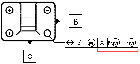
Frames
Create additional frames. You can define as many frames as required. Use the Frames box to move among frames. You can see only two frames in the dialog box at a time.
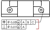
Composite Frame
Combines the symbols of two frames.
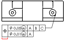
Below Frame
Add text below the feature control frame.
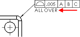
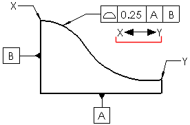
Between Two Points
Type the labels of the points if the tolerance value applies between two points or entities.
