Properties specific to sheet metal parts are calculated and displayed in the Cut-List Properties dialog box.
Some of the properties that are calculated are based on the bounding box, the smallest rectangle in which the flat pattern can fit. You can set a grain direction to determine the smallest rectangle that aligns with the grain direction to fit the flat pattern (see Flat-Pattern PropertyManager).
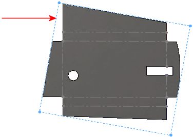
The bounding box is represented by a sketch when you flatten the sheet metal part and is located in the FeatureManager design tree under Flat-Pattern  . You can also create a bounding box for any cut list item in a cut list, independent of the type of solid or sheet metal bodies in the cut list item.
Example of bounding box sketch in a flat pattern:

The following properties are calculated in sheet metal parts:
| Bounding Box Length |
Longest side of the bounding box |
| Bounding Box Width |
Shortest side of the bounding box |
| Sheet Metal Thickness |
|
| Bounding Box Area |
Bounding box length x Bounding box width |
| Bounding Box Area-Blank |
Area of the flat pattern excluding the through cut-outs |
| Cutting Length-Outer |
Outer perimeter of the flat pattern (blank), which is used for calculating the machine’s cutting time |
| Cutting Length-Inner |
Sum of the perimeters of internal loops or cut-outs |
| Cut Outs |
Closed cut outs (through holes) on the flat pattern, which are used for calculating the machine’s idle time |
| Bends |
Number of bends in the part |
| Bend Allowance |
Basis of the flat pattern calculation |
| Material |
|
| Mass |
|
| Description |
|
| Bend Radius |
|
| Surface Treatment |
|
| Weight |
Calculates the Mass (mass based on the folded mass) or Flattened-Mass (mass based on the model's flat pattern) |