You
can
model flexible or folded ribbon cable routes.
Before Starting the Route
Recommended practices:
- In the main assembly, define geometry to which you will mate the ribbon cable connectors. For example, model mating sockets for the connectors, and insert them in the main assembly. Use matching mate references to assure that you can easily mate the connectors to the sockets when you insert the connectors in the route.
- Place clips or virtual clips in the main assembly, so you can select their axes to route through.
Starting the Route
To start a ribbon cable route, insert a valid ribbon cable connector into an existing assembly by any of the following methods:
- Drag from the Design Library.
- Drag from Windows File Explorer.
- Click Insert Component
 (Assembly toolbar).
- Click Insert Connectors
 (Electrical toolbar).
When you drop a connector in the graphics area, the following happens:
- A 3D sketch opens in a new route subassembly.
- The Auto Route PropertyManager opens.
- The new route subassembly is created, and appears in the FeatureManager design tree.
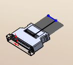
- A stub of ribbon cable appears, extending from the connector you just placed.

Defining the Route
Use tools and options in the Auto Route PropertyManager to define the route between the two ribbon cable connectors.
Under Auto Route, select Folded or Flexible.
Under
Routing Mode, switch among modes to perform different tasks.
| Mode |
Tasks |
| Auto-Route |
Automatically extend the route by clicking route end points and axes of clips. |
| Edit (drag) |
- Right-click a route segment and select Delete so you can define a different path for that section of the route.
- Right-click a connection point and select Add to Route.
- Drag construction lines on splines to modify the twists in cables.
|
| Manual sketch |
Sketch lines to extend the route in the 3D route sketch. |
All sketch tools are available when you create and edit ribbon cable routes, like other routing functionality. To use the sketch tools, open the ribbon cable assembly and right-click in the graphics area. You can add or delete segments, and add or delete dimensions.