| Use
shaded face highlighting |
Displays the selected faces in a
solid color (green by default). To specify a
different highlight color, from the System Options dialog box, click Colors and modify the current
color scheme.
Some third-party
applications might require that you clear this
option.
|
| Highlight all edges of features selected in graphics
view |
Highlights all edges of a feature
when you select the feature. |
| Dynamic highlight from graphics view |
Highlights model faces, edges, and
vertices when you move the pointer over a sketch, model, or drawing.
Available when Large Assembly Settings is off.
|
| Display temporary axes upon hover over cylindrical
faces |
Controls whether temporary axes
appear when you hover over cylindrical faces. The default is
enabled. |
| Show
open edges of surfaces in different color |
Makes it easier to differentiate
between the open edges of a surface and any tangent edges or
silhouette edges. To specify the
edge color, click . Select in System
colors.
|
| Display shaded planes |
Displays transparent shaded
planes with a wireframe edge that have different front and back
colors. To specify the shaded
plane colors, click . Under Faces, select Front
Face Color or Back
Face Color to change the colors. Move the slider
to the right for more transparency.
|
| Display dimensions flat to screen |
Displays dimension text in the
plane of your computer screen. Clear to display dimension text in
the plane of the dimension's 3D annotation view.
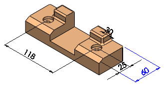 |
| Selected:
Dimension text is in the plane of your computer
screen, and all dimension text and lines in the
current annotation view are visible. |
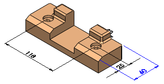 |
| Cleared:
Dimension text is in the plane of the 3D
annotation view, and dimension text and lines that
are behind the model are hidden. |
|
| Display notes flat to screen |
Displays notes in the plane of
your computer screen. Clear to display notes in the plane of the
dimension's 3D annotation view. |
| Display reference triad |
Displays a reference triad to help
orient you when viewing models. The reference triad is for display
purposes only. You cannot select the triad or use it as an inference
point. |
| Display scrollbars in graphics view for parts and
assemblies |
You cannot change this option while any
SOLIDWORKS documents are open.
Turns scrollbars on in the graphics view of part
and assembly documents.
To use accelerated zoom, clear this option and
press Shift + mouse
wheel in the graphics area.
|
| Display scrollbars in
graphics view for drawings |
You cannot change this option while any
SOLIDWORKS documents are open.
Turns scrollbars on in the graphics view of
drawing documents.
|
| Display draft quality ambient occlusion |
Uses draft quality for rendering
models when you use Ambient
Occlusion. Draft quality renders faster but has less
visual fidelity. Clear to use the default quality. |
| Display SpeedPak graphics circle |
Enables or disables the display
of the SpeedPak graphics circle. When you enable
the graphics circle, only selectable geometry is visible in the
region surrounding the pointer.
When you
disable the graphics circle, all geometry in the region
surrounding the pointer remains visible.
|
| Display Pattern Information Tooltips |
Displays information about a
pattern including pattern name, pattern type, all seeds used to
create the pattern, spacing and number of instances, instances
skipped, and instances varied. |