The Orientation Tolerances option allows TolAnalyst to consider tolerances that explicitly control feature orientation. When combined with the option, Float fasteners and pins, the Orientation Tolerances option allows TolAnalyst to use the clearances between features to rotate parts into their worst-case condition.
Supported tolerances:
- Angularity
- Parallelism
- Perpendicularity
- Angle dimensions defined using the Location Dimension
 tool.
tool.
The
Orientation Tolerances option does not consider these tolerances that implicitly control feature orientation: position, surface profile, and linear dimensions defined using the
Location Dimension 
tool.
Example 2
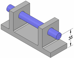
| Using this assembly, create a study to evaluate the distance from the base to the shaft as shown by the 35 dimension.
|
 |
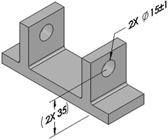
| Apply the size tolerance shown to the two holes in the base.
|
 |
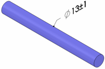
| Apply the size tolerance shown to the diameter of the shaft.
|
 |
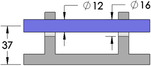
| With Float fasteners and pins selected and Orientation Tolerances cleared, the results are a minimum of 33 and a maximum of 37 (shown). Note how the shaft pushes up against the tops of the holes.
|
 |
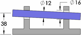
| With Float fasteners and pins and Orientation Tolerances selected, the results are a minimum of 32 and a maximum of 38 (shown). Note how the shaft is rotated such that it contacts the top outside edge of the left hole and the bottom outside edge of the right hole.
|
 |