 |
General |
Creates a cooling channel by entering the diameters at
the two end nodes connected by line elements. |
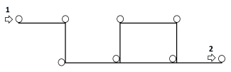 |
| Schematic representation of a cooling channel layout. 1: Input Node, 2: Output Node
|
 |
Baffle |
Creates a cooling channel by entering one diameter for
the two end nodes. The bottom node connects to the node of a line
element, and the top node is isolated. |
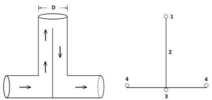 |
| Schematic representation of a Baffle cooling
channel. 1: Top Node, 2: Baffle, 3: Bottom
Node, 4: Channel Element
|
 |
Bubbler |
Creates a cooling channel by entering two diameters
(tube cross-section) for the two end nodes. The bottom node connects
to the line element and the top node is isolated. |
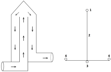 |
| Schematic representation of a Bubbler cooling
channel. 1: Top Node, 2: Bubbler, 3: Bottom
Node, and 4: Channel Element
|
 |
Flip
Inlet |
Reverses the inlet direction. |