| Peripheral |
Creates a circle  at the bend in the weld line to indicate that the weld is applied all around the contour. at the bend in the weld line to indicate that the weld is applied all around the contour. |
| Field/Site |
Adds  at the bend in the weld line to indicate that the weld is applied in the field or on-site. Select the lower Field/Site to point the flag down. at the bend in the weld line to indicate that the weld is applied in the field or on-site. Select the lower Field/Site to point the flag down. |
| Weld symbol |
Use the upper Weld symbol button to select a symbol for a "this side" weld. Use the lower Weld symbol button to select a symbol for an "other side" weld. Click and select a symbol from a symbol library. To turn off the symbol, clear it by toggling it off. Other options become available, depending on the symbol you choose. Type a size to the left of the symbol. Type a pitch to the right of the symbol. Pitch format is usually Length-Pitch.
 |
 |
| "Other side" weld |
"This side" weld |
The ISO standard uses the weld symbols on (above) the line for a "near side" or "this side" weld and weld symbols on the dashed line (below) for a "far side" or "other side" weld by default. If you change the drafting standard to ISO, the software changes the weld symbols.
|
| Specification process |
Type text in the large box at the right, in any number of lines, to appear in the tail of the symbol.

|
| Reference |
Creates a reference box around the Specification process text. |
| Contour |
Applies a contour shape above the symbol. |
| Groove Angle |
(JIS only) Type an angle in degrees (degree symbol is added automatically).
|
Inside
|
Places text inside the weld symbol.
|
|
| Root Opening |
(JIS only) Type a dimension. |
| 2nd fillet |
Adds a second fillet to the existing symbol. This option is available for Square Butt, Single Bevel Butt, Single Bevel Butt with Root, and Single J Butt only. Type a size to the left of the symbol. Type a pitch to the right of the symbol. |
| Symmetric |
Properties on one side of the symbol line also appear on the other side. |
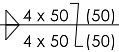
| Stagger |
Adds the symbol for staggered intermittent welds:

Specify the weld details in the fields to the right of each Weld symbol button.
- In the first box, enter the number and length of the weld elements; for example, 4 x 50.
- In the second box, enter the distance between each weld element; for example, (50).
 |
| Identification line on the top |
Moves the dashed identification line above the symbol line. |
| Font |
To specify a font for text and size of symbols, clear Use document font and click Font. |
| Leader anchor |
Anchor the leader to the specified location on the weld symbol. |
| Use multi jog leader |
Allows you to click in the graphics area several times to create bends for the leader. |
| Layer |
In a drawing with named layers, choose a layer from the list. |
| Include this symbol in weld table |
Select to make the weld symbol available for the weld table. |
| Style |
To modify weld symbol style options. For details, see Style. |
| Leader Style (in the Weld Symbol PropertyManager) |
Use document display:
- Select to use the weld symbol document properties configured in .
- Clear to specify leader style
 or thickness or thickness  . .
|