SOLIDWORKS Electrical Schematic
- Exercise #05
This exercise allows you to manipulate the existing objects and to create
the first terminal strip. It is based on the electrical project you made
in the Exercise #04. If you did
not complete it, you can download the electrical project file and unarchive it in SOLIDWORKS Electrical.
If this is your first time, open the PDF file of the exercise to read
through it. Printing it out is recommended.
Handling objects
Modify the M1 motor circuit so that it complies with the model (Appendix
4a).
1. Select the motor symbol and the wires vertically
above it using the "Capture" mode of selection. Move the set
underneath the contactor symbol. Delete any superfluous wires.

|
Menu:
Schematic > Move |
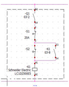
Duplicate the M1 motor circuit using the Copy command.
1. Select the entire motor circuit. Click on the Multiple copy icon in the Schematic menu. Click the starting
point and the destination point.

|
Menu:
Schematic > Multiple copy |
The component marks increment automatically. Manufacturer
parts are retained. |

Inserting
a black box
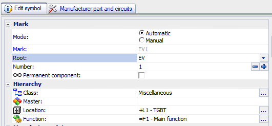
Insert the EV1 variator (black box), associate it with the Miscellaneous
class and modify its material terminals.
1. Click on the Insert
black box icon in the Schematic
menu.

|
Menu: Schematic >
Insert black box |
2. Allocate the Miscellaneous
class.
3. Change the root to EV.

4. To modify the numbers of material terminals, use
the command Edit symbol terminals
in the black box contextual menu.

|
Black
box contextual menu: Edit
symbol terminals |
5. Change the material terminal numbers in the Mark column.

Copying
existing elements
If you want to move or
copy part of a scheme, you can use a copy/paste ([Ctrl]+[C]
- [Ctrl]+[V]) or save it as a macro. Macros
should be used for repetitive elements. |
Copy/Paste.
Move the K1 command circuit on a new scheme (Mark: 04 - Description: Command).
1. Select the entities
using the Capture or Selection
mode.

2. Use the [Ctrl]+[C] keys to Copy
the selected entities.
3. Create and open
the drawing 04.
4. Plot the high
and low polarity wires (48VDC) and the circuit with the reversing switch
contact in column 6 (Appendix 5b).
5.
In the drawing 03, delete the K1
command circuit.
6. Use the [Ctrl]+[V] keys to Paste
in the drawing 04 the copied entities.
7. In the drawing
04, review and adapt the symbol marks using the symbol properties.

|
Contextual menu of a symbol: Symbol
properties |
8. Enlarge the assembly
to obtain a close-up view of the model (Appendix 5b).
The Copy/Paste
command is not the best way to move entities from one drawing
to another. With this command, you need to delete the existing
entities and manage component marks. It could be better to use
the Cut/Paste command. |
Copy/Paste
special. In the drawing 04, copy the K1 command circuit in column
04 and readapt the marks.
1. Use the [Ctrl]+[C] keys to copy the entities.
2. Use the [Ctrl]+[Shift]+[V] keys for pasting
the selected objects.
3. Manage the object
marks to be consistent with the appendix 5b. Associate the Q2
and K2 contacts to the Q2
and K2 components of the drawing
03.
Using
a macro. In the drawing 04, delete the K2 command circuit and create
a macro composed of the K1 command circuit and insert it in column 04.
1. After deleting
the entities, select the entities of the K1 command circuit and drag them
to the Command group in the Macros tab in the dockable panel.

2. To insert the
macro, drag it from the dockable panel to the graphical area.
3. As the Paste
special command, manage the component marks.
A macro is similar to a Copy/Paste special in which
the graphical objects are saved in the Macro
management, to be re-used. |

Circuit management
Both symbols and manufacturer
parts have got circuits. Each pole of a device is associated with
a circuit and manage them is very important to have a good result
for the cross references, material terminal display... |
Swapping the material terminals.
Modify drawing 04 so that the material terminals of the K1 NO contact
are 83/84 instead of 53/54.
1. Edit the K1
component and go into the Manufacturer
part and circuits tab.

|
Contextual menu of a symbol: Symbol
properties |
2. In the list of circuits, drag contact (53-54) to contact (83-84).

Inserting
terminals
Place the XA1 and XM1 terminals on drawing 03.
1. Draw the location outline around the motors.
2. Use the Insert
'n' terminals command in the Scheme menu.

|
Menu: Schematic > Insert
'n' terminals |
2. Plot a perpendicular axis to the 2 motor circuits.
A terminal is drawn at each intersection.
3. Select the XA1
terminal strip in the right-hand part of the mark dialog box.
4. Ensure that the terminal mark is 1.
5. Click on OK (All
terminals) to validate.
6. Repeat the operation to draw the terminals for
terminal strip XM1.
Add the EV1 component to the XA1 terminal strip.
A component can be an element of a terminal strip such as
a terminal and can be easily added. |
1. Use the contextual menu of the symbol to add the
component to a terminal strip.

|
Contextual menu of a symbol: Component
> Insert in terminal strip |
2. In the terminal strip selector, select the XA1
terminal strip.
3. The component is added at the end of the terminal
strip.
4. In the EV1
contextual menu, select the Edit terminal
strip "XA1". Remove EV1
from the terminal strip by selecting the Extract
from terminal strip command in the contextual menu of EV1.
