To open this PropertyManager:
- Create a sketch.
- Click one of the extrude tools:
 |
Extruded Boss/Base |
on the Features toolbar, or click
|
 |
Extruded Cut |
on the Features toolbar, or click |
 |
Extruded Surface |
on the Surfaces toolbar, or click |
Set the PropertyManager options based on the type of extrude feature.
From
Sets the starting condition for the extrude feature.
Direction 1
Some fields that accept numeric input allow you to create an
equation by entering = (equal sign) and selecting global variables, functions, and
file properties from a
list.
See Direct Input of Equations in
PropertyManagers.
| |
Direction 1
|
Determines how the feature extends. Set the end condition
type. If
required,
click Reverse Direction
 to extend the
feature in the opposite direction from that shown in the preview. to extend the
feature in the opposite direction from that shown in the preview.
|
Blind
|
Set the Depth  . .
|
|
Through All
|
Extends the feature from the sketch
plane through all existing geometry.
|
|
Through All - Both
|
Extends the feature from the sketch
plane through all existing geometry for Direction 1 and
Direction 2.
|
|
Up to Next
|
Extends the feature from the sketch plane to the next
surface that intercepts the entire profile.
|
|
Up to Vertex
|
Select a vertex in the graphics area for
Vertex  . .
|
|
Up to Surface
|
Select a face or plane to extend to in
the graphics area for Face/Plane
 .
Double-click a surface to change the End Condition to
Up to
Surface, with the selected surface as the
termination surface. If the sketch that you extrude
extends outside of the selected face or surface body,
Up To Surface
can do some automatic extension of one analytic face to
terminate the extrusion. .
Double-click a surface to change the End Condition to
Up to
Surface, with the selected surface as the
termination surface. If the sketch that you extrude
extends outside of the selected face or surface body,
Up To Surface
can do some automatic extension of one analytic face to
terminate the extrusion.
|
|
Offset From Surface
|
Select a face or plane in the graphics
area for Face/Plane
 , and
enter the Offset
Distance , and
enter the Offset
Distance
 .
Select Translate
surface to make the end of the extrusion
a translation of the reference surface, rather than a
true offset. If
required,
select Reverse
offset to offset in the opposite
direction. Example: Translate Surface .
Select Translate
surface to make the end of the extrusion
a translation of the reference surface, rather than a
true offset. If
required,
select Reverse
offset to offset in the opposite
direction. Example: Translate Surface
|
|
Up To Body
|
Select the body to extrude to in the
graphics area for Solid/Surface Body
 . You
can use Up To
Body when making extrusions in an
assembly to extend the sketch up to the selected body.
Up To Body is
also useful with mold parts, if the body you extrude to
has an uneven surface. . You
can use Up To
Body when making extrusions in an
assembly to extend the sketch up to the selected body.
Up To Body is
also useful with mold parts, if the body you extrude to
has an uneven surface.
|
|
Mid Plane
|
Set the Depth  . .
|
|
 |
Direction of Extrusion |
Select a direction vector in the graphics area to extrude the sketch in a direction other than normal to sketch profile. Example: Specifying the Direction of Extrusion |
| |
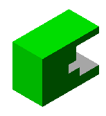
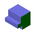
Flip side to cut |
(Extruded cuts only). Removes all material from the outside of the profile. By default, material is removed from the inside of the profile.
 |
 |
| Default cut
|
Flip side cut
|
|
| |
Normal cut |
(Sheet metal cut extrudes only). Ensures that the cut is created normal to the sheet metal thickness for folded sheet metal parts.
|
| |
Merge result |
(Boss/Base extrudes only). Merges resultant body into an existing body if possible. If not selected, the feature creates a distinct solid body.
|
| |
Link to Thickness |
(Sheet metal parts only). Automatically links the depth of an
extruded boss to the thickness of the base feature. The Link to
thickness option in the Extrude PropertyManager lets you
link the dimension of the present extrusion to the dimension of
the existing extrusion to which it is coincident. If the depth
of the original extrusion changes, the new
extrusion
changes to match it.
This is available
only when sheet metal features are present in the FeatureManager
design tree. The Link to
thickness option is useful in sheet metal parts
because the part must be of uniform thickness.
|
 |
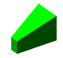
Draft On/Off |
Adds draft to the extruded feature. Set the Draft Angle. Select Draft outward if
required.
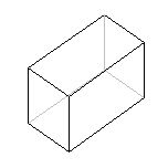 |
| No draft |
 |
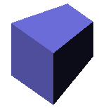 |
| 10° draft
angle inward |
10° draft
angle outward |
|
Direction 2
Set these options to extrude in both directions from the sketch plane. The options are the same as Direction 1.
Thin Feature
Use the
Thin Feature options to control the extrude thickness (not the
Depth 
). A
Thin Feature base can be used as a basis for a sheet metal part.
Example: Extruding Thin Features
Thin Feature is required when using an open contour sketch. Thin Feature is optional when using a closed contour sketch.
| |
Type |
Sets the type of thin feature extrude.
|
One-Direction
|
Sets the extrude Thickness  in one direction (outward) from the sketch. in one direction (outward) from the sketch.
|
|
Mid-Plane
|
Sets the extrude Thickness  equally in both directions from the sketch. equally in both directions from the sketch.
|
|
Two-Direction
|
Allows you to set different extrude thicknesses for Direction 1 Thickness  and Direction 2 Thickness and Direction 2 Thickness  . .
|
|
| |
Auto-fillet corners |
(Open sketches only). Creates a round at each edge
where
the lines meet at an angle.
|
Fillet Radius 
|
(Available if Auto-fillet corners is
selected). Sets the inside radius of the round.
|
|
| |
Cap ends |
Covers (caps) the end of the thin feature extrude, creating a
hollow part. You must also specify the Cap Thickness
 . This
option
is available only for the first extruded body in a model. . This
option
is available only for the first extruded body in a model. |
Feature Scope
Specifies which bodies or components you want the feature to affect.
- For multibody parts, available if you select Geometry pattern under Options. See Feature Scope in Multibody Parts.
- For assemblies, see Feature Scope in Assemblies.