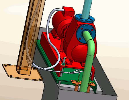
Routing cables generates
a 3D representation of the cable path within an electrical installation.
The routing paths and connection points facilitate the routing process.
Segregation manages the rules applied to cable paths.
To access Routing Cables:
- SOLIDWORKS Electrical 3D menu: Route Cables
 .
.
- Menu:
 .
.
When
you run Routing Cables, the left dockable
panel changes to display the options of the command. Several of
these parameters are saved in the SOLIDWORKS Electrical file and are specific to the
file. The others are saved in the registry and are common to all SOLIDWORKS
Electrical files.
Routing Analysis
Show errors. Displays a report at the
end of the routing that shows all routing errors. Click Help on a line of the report for information about the error.
Select route type
- SOLIDWORKS Route.
Routes the cables as managed by SOLIDWORKS, accounting for cable
diameters.
- 3D Sketch Route.
Routes the cables as a 3D sketch. This mode is quicker and better for
temporary routings.
- Update
Origin/Destination. Updates the cable properties about their
origin and destination.
- Cable cores follow routing
path: By default, cable cores are directly routed. This
option uses paths to route them.
Select renderer type
- Use splines. Uses splines (curves)
to ensure optimal rendering of the cable routing. When you use splines in
the routing path, you can manually add points on it to improve the
routing.
- Use lines. Generates cable routing
with straight lines.
- Add Tangency. Inserts curves at the
end of the straight lines.
Cables to route
- All cables. Launches routing across
all cables of the electrical project.
- Route active location only. Limits
the routing of cables to the top-level assembly only.
This supports creating SOLIDWORKS Route and 3DSketchRoute route types.
- If the cables at the top-level active
location have their origin or destination components in
another location or sublocations of the electrical
project, only those cables get routed along with the
cables belonging to the components of the active
top-level location.
- If the cables at the top-level active
location have their origin or destination components in
another location that is out of scope (for example, the
active location is a sublocation, and a cable is at the
top location), the cable is not routed.
- Selected components.
Launches routing across a subsection of the components. Select the
components in the graphics area. Only the cables connected to the selected
components are routed.
- Selected cables. Lets
you select the cables to route. You cannot select harness cables. Only the
selected cables are routed; the other routed cables are not modified.
Right-click the list to manage the cables.
Routing parameters
The first parameter specifies the distance between two routing paths.
The second parameter specifies the distance between a connection point and routing
path. The third parameter specifies the distance between two cables.
The graph lets you quickly view connections between components. There
are two options available:
one
for display, and the other for deleting the graph.
