You
can create multiple display states for each configuration of an assembly or
part.A
physical product can have only one display state.
To control display states in a design table, you must link
display states to configurations.
At
the bottom of the
Display States section
in the ConfigurationManager: CAD Family

tab or the ConfigurationManager

tab, right-click a display state
and click
Properties.
In the
Display State Properties
PropertyManager, under
Advanced Options,
select
Link display states to
configurations. Click

.
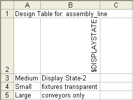
In a design table, the column header for controlling the active
display state uses this syntax:
$DISPLAYSTATE
The column header is not
case-sensitive.
In the table body cells, enter the display state name. If a
cell
remains blank:
- For new configurations, the system adds Display State-n to the table.
- For existing configurations, the system adds the name of
that configuration's
last
active display state.
Example of a design table that controls the display state of assembly
configurations:
