In
this exercise, you update a 3D assembly
for
compatibility
with the SOLIDWORKS Electrical 3D processes for cabinet layouts and routing. A wizard helps
you manage the cable and wire connection points, define the faces, and
assign mate
references.
First, download the Exercise
1 electrical project, unzip it to a local drive, then unarchive it.
Defining the Faces and Rail Mates
- In SOLIDWORKS,
click
and
browse to
EW4SW_Exercise01.proj\Projects\2\SolidWorks\lc1d1210b7_ew.SLDPRT.
- Click
 to start the Routing Component Wizard.
- On the Mate Reference
tab,
under Component Alignment
Options,
click Define Faces.
- In the
Define all the faces of the component
PropertyManager,
for each of the four selection zones, click the corresponding face of the
component, then click
 to define the faces.
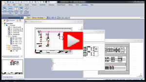
See
the video for
details.
- In
the Routing Component Wizard,
define
the rail mates:
- On the Mate
Reference tab, under Reference Name, click For
Rail and
for
Optional Mate Reference,
click
Add.
- In the
Create mate reference
PropertyManager,
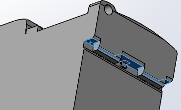
for Top face of the rail, select
the face
shown.

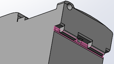
- For Front face of
rail, select the face
shown.

- Click
 to define the rail mate
references.
- Click
Save
&
Finish.
Keep the Routing Component Wizard open for the next task
where you create connection points.
Creating the Connection Points
- In the Routing Component Wizard, on the Routing Functionality Points tab, under
CPoint
Type, select CPoint from
Manufacturer
part
and
click
Add.
- In the
CPoint from Manufacturer Part
PropertyManager,
under Selected Manufacturer Part, click
Browse.
- In the
Manufacturer part selection dialog box:
- On the Filters
tab, under Manufacturer part,
for Manufacturer, specify
Schneider Electric.
- For Reference,
enter lc1d12.
- Under
Classification,
for
In the class, click
Any class.
- Click Search
 .
.The system finds the required component.
- Click
the component and click Select.
In
the PropertyManager,
Terminal List is populated
but the
CPoints
are
not
assigned
yet.
- Click
 to pin
the PropertyManager
open.
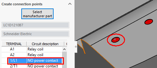
- Under Terminal List,
select the first item under Mark, then
select the corresponding component terminal entity in the
graphics
area.

The
selection appears under Selected
Entity.
Under
CPoint Name, the list displays
the selected entity.
- Click
 .
.Under CPoint Name,
the list displays the selected
entity.
- Repeat steps
5
and
6
to create all the connection points.

- Close
the
PropertyManager,
then
close
the wizard and save the file in the SOLIDWORKS folder of the
electrical
project.
You use this part again in Exercise
2.