In this exercise, you unarchive an electrical project and insert
ducts, rails, and components into a cabinet.
First, download the Exercise
1 electrical project, unzip it to a local drive, then unarchive it.
Inserting the Cabinet
- In the Task Pane, on the SOLIDWORKS
Electrical 3D tab, expand item 1, right-click the Cabinet assembly, and click Open.
The SOLIDWORKS
Electrical Manager opens in the left pane.
- Right-click
178864 (the cabinet) and click Insert.
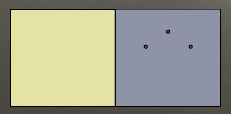
- In the graphics area, drag the cabinet and click to position it,
then click
 .
.
Inserting the Ducts and Rails
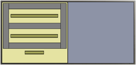
You first insert the five ducts, which are sized to the required
value. The first three entities are horizontal ducts and the last two are vertical
ducts. Place the ducts approximately as shown in the video and use mates to position
them. You then insert three vertical rails.
- In the SOLIDWORKS Electrical Manager, right-click
36212 and select Insert as horizontal duct.
- Drag the duct to position it in the graphics area, then click
 in the shortcut menu and
in
the PropertyManager.
- Repeat steps 1 and 2 for the first
three
ducts shown in the SOLIDWORKS Electrical Manager.
- Repeat
steps 1 and 2 to position the two vertical ducts. This time
select
Insert as vertical duct.
- In the
SOLIDWORKS
Electrical Manager, right-click
178864 and click Hide to display only the ducts.
- In the Assembly
CommandManager, click Mate
 and create five coincident
mates and one distance
mate as
shown in the
video.
- Close the Mate PropertyManager and
Show the cabinet.
- Repeat steps 1 and 2 for the three rails. This time
select
Insert as horizontal rail for each
rail.
Insert the rails in order from top to
bottom.

Inserting the Components
There are several
tools
available to insert the components.
To complete this exercise,
you must have completed
SOLIDWORKS
Electrical 3D
Exercise - 1, which created the required connection points and determined the
faces and mates.
To insert the components:
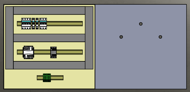
- In the SOLIDWORKS Electrical Manager, right-click
T1
and
select Insert.
- Drag the component to position it on the middle rail as shown in
the video.
- In the
SOLIDWORKS
Electrical Manager, right-click
KM1
and select Insert from file.
- In the Open dialog box,
browse to select
EW4SW_Exercise01.proj\Projects\2\SolidWorks\lc1d1210b7_ew.SLDPRT.
- Drag the component to position it on the middle rail next to the
T1 component.
- In the
SOLIDWORKS
Electrical Manager, multiselect components Q1, Q2,
Q3, and Q4, right-click, and select Insert.
In the
Insertion order dialog
box,
you can change the insertion order if
required.
- Accept the default order by clicking OK.
- Drag to position the first component on the top
rail.
- In the
Multiple Insertion PropertyManager:
- Under Multiple Insertion, click
Right for the
direction.
- Under Spacing, enter 10.
- Click
 .
.
The software inserts the four components from left to right
and spaced 10mm
apart.
- In the
SOLIDWORKS
Electrical Manager, right-click
X1
and select
Insert terminals.
The X1 component consists of
multiple terminals that you insert with a direction and spacing as you did
in the previous step.
- Drag the component to position it on the bottom rail and click
 .
.
- In the Insert
terminals
PropertyManager,
under Multiple Insert:
- Click Right.
- Enter 0 for Spacing.
- Click
 .
.
The software positions seven terminals next to each
other.
- Click Back
 .
.
- Insert
the S1, S2, and H1 components
on the cabinet door as shown in the video.
- Rotate the model to view the opposite side of the cabinet door.
- On the Assembly tab of the CommandManager,
use the Mate
 tool to add coincident mates
for the three components and their holes.
- Click
Front
 .
.
- Use the Mate tool to add parallel mates
between the three components and the cabinet door edge as shown in the
video.

Keep this project open because you use it again in Exercise 3.