In this exercise, you learn how to manage several types of symbols, such
as the wiring line diagram and schematic symbols. You create a PLC symbol from its
manufacturer part.
For reference while following this exercise, open, or download and print this PDF document.
Line Diagram Symbol
Ensure that the
Emergency stop symbol
is compatible to insert in a line diagram drawing.
- Click
 .
.
- Click Filters and
enter the details for all the fields.
- Select the Emergency
stop symbol and click Open.
You can also double-click the icon
to open it.
- Click to place a rectangle around the symbol.
Without this rectangle, the wires or cables cannot snap onto the
symbol.

Schematic Symbol
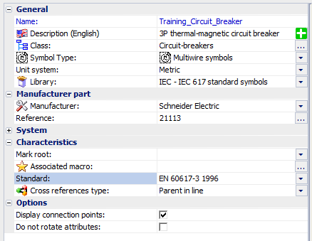
Create a 3P thermal-magnetic circuit breaker-type symbol in compliance with
Appendix 13a with these parameters:
- Name: Training_Circuit_Breaker
- Belong to the IEC library
- Drawn using Metric units
- Declared as a parent in line symbol
- Automatically associated with the 21113 part from
Schneider
- Propagate the cross-references, the current rating, and the
magnetic current setting
- Click .
- In the Symbols manager, under
Classification, click .
- Click New.
- Enter these properties:

- Click OK to create the symbol.
An empty thumbnail appears in the right side of the dialog
box.
- Select the empty thumbnail and click Open.
The Training_Circuit_Breaker opens in the graphics
area.
- Click .
Ensure that the coordinates for the first
point are at (0,0) and the second point are at (10,15).
- Draw the first pole of the circuit breaker, using the rectangle.
- Click
 .
.
- Click
 .
.
- Specify the snap spacing so that the connection points have the same
intervals as the distance between the wires (5mm by default).
- Right-click the lock bar to open the Drawing support dialog
box.
- Specify the snap and grid settings:
- Delete the rectangle.
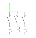
- Create poles 2 and 3 of the circuit breaker by copying the first pole.
With the snap spacing locked, the poles are equidistant at
5mm.
- Add the axis line.
- Click .
- Click .
- Click .
- Click to move the assembly so that the connection highest and furthest
to the left is on the axis marker (double green arrow at coordinates
(0,0).

- Click
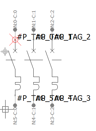
 to add 3 disconnectable
Circuit breaker/Switch
circuits.
- Select circuit 0 and click
 to insert the connection
points.
 The connection point block is attached to the
pointer. It comprises a line and two circles.
- Press [Space] to rotate the connection point.
- Insert the connection point so that the white circle coincides with the wire
connection point.
- Insert the five other connection points, selecting the corresponding
circuits.

The dockable panel displays the properties of the
connection points and allows you to correct any allocation errors. In each
circuit, the number of the points in the upper part must be less than the
number of points in the lower part.
- Click
 to insert the attributes.
- In the Attributes management dialog
box, specify these attributes to insert on the symbols:
- Insert the attributes near the symbol.
You can use the
attribute Properties to modify the
font, height, and justification.
- Close and save the symbol file.
- Check the result by inserting the symbol in a scheme drawing.
