The routing paths define
the path the wires or cables use for routing. Without these paths, the software routes the
wires or cables the shortest path between the components regardless of the installation
mates.
The placement of routing paths is mandatory for coherent routing.
To
define routing paths:
-
Do one of the following:
- SOLIDWORKS Electrical 3D menu: Click Define
Routing Path
 .
.
- In the menu, click
 .
.
When you run Define Routing Path,
the panel displays the options for creating routing paths. The routing path is
based on sketches, where you can use lines, arcs, and splines.
-
In the Define Routing Path
PropertyManager, under Action,
click:
- Create sketch to
create a new sketch.
- Convert sketch to
use an existing sketch. You can select one or several sketches.
-
Under Sketch color,
click Select color to choose a new
color.
To differentiate SOLIDWORKS sketches from routing sketches, you can
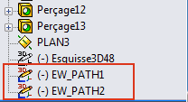
select a sketch color. The sketches representing the routing paths are named
EW_PATH <
order number>.

You do not have to join the routing paths between sketches.
When you launch the routing, parameters manage connection tolerances. You
can integrate these routing paths into the subassemblies, as ducts for
example.