This topic explains the parameters in the default IEC configuration for terminal
strip drawings.
You generate terminal strip drawings by inserting symbols. You can use the default
symbols, or use symbols associated with the manufacturer parts or scheme symbols.
The SOLIDWORKS Electrical draws elements like text, attributes, and graphical
representations of cables according to configuration parameters.
A terminal strip drawing configuration file contains all the parameters of the
terminal strip layout, grouped by theme. You can create as many configuration files
as you need. Configurations are grouped within the Terminal strip drawing
configuration management dialog box.
The configuration file editor displays a preview of the selected parameters. You can
deactivate the preview by selecting the Drawing preview check
box in the bottom of the Terminal strip drawing configuration
dialog box.
General
This tab lets you name the configuration file and give it a description in any of the
languages supported by the software. Changing a name automatically updates it in all
interfaces (for example, Configurations, or the list of terminal strips).
| Name |
Description |
| Name |
The name of the configuration file. This value
automatically propagates to all interfaces in which the configuration
appears. |
| Description |
Description of the configuration. You can specify a
description in multiple languages. |
Terminals
This tab displays the parameters defining the graphical representation of
terminals.
| Name |
Description |
| Terminal dimension |
You can specify the width A and height
B of the terminal. They stay the same,
regardless of the terminal strip orientation (horizontal or
vertical).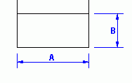 |
| A Width |
Width A of the terminal. |
| B Height |
Height B of the terminal. |
| Accessory terminal |
You can insert an accessory to the terminal strip, such as a
separator or stop element. The accessory appears in the terminal strip
as a terminal but without a mark. You can specify the width
C and height D of the
accessory. They stay the same, regardless of the terminal strip
orientation (horizontal or vertical). |
| Insert accessory terminal |
Lets you insert an accessory to the terminal strip. |
| C Width |
Width C of the accessory. |
| D Height |
Height D of the accessory. |
| Earth collector |
You can connect all unused cable cores to an earth collector.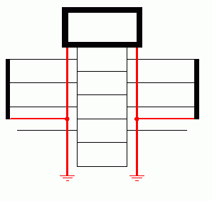
|
| Active earth collector |
Lets you connect all unused cable cores to the earth
collector. |
| E Collector spacing |
Collector spacing distance
E separating the earth collector from the row
of terminals.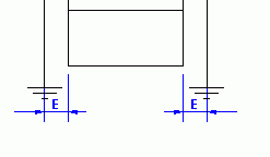 |
| Connect all unconnected cable cores to earth
collector |
Lets you connect all unconnected cable cores to the earth collector,
even if they are not Green/Yellow. |
| Multiple level
terminals |
Multilevel terminals are specific terminals on which you can connect
several wires or cable cores. They have several circuits, unlike the
single terminals that have only one circuit. |
| Width of last level (%) |
Indicates the scale factor (in %) between the first and the last
level of the multilevel terminal. SOLIDWORKS Electrical calculates the
width of the intermediate levels automatically. |
| Line thickness |
The thickness of the outline of the multilevel terminal. |
| Color |
The color of the multilevel terminal. |
Symbols
You can draw terminal strips by stacking up symbols (for example, header symbols or
terminal symbols). This tab lets you select, edit, or delete the symbols, allowing
the generation of terminal strip drawings.
| Name |
Description |
| Custom symbol |
You can draw the terminal strip with the default
terminal symbols, or with custom terminal symbols. If SOLIDWORKS
Electrical does not find an association, it automatically switches
to the other known association. If no association exists, SOLIDWORKS
Electrical uses the default symbol defined in the
configuration.
|
| Insert custom symbol |
If cleared, SOLIDWORKS Electrical uses the generic
terminal symbols corresponding to the different types of terminals to
generate the terminal strip drawings. For each of these terminals, you
must select the terminal symbol to use in the terminal strip drawing,
and define their orientation and their scale. In the properties of
a manufacturer part or a symbol, you can find two parameters
allowing you to associate a Terminal type or a Terminal strip
symbol.
|
| Priority - Manufacturer part / scheme symbol |
Specify whether you want to prioritize the
Manufacturer part or the Scheme symbol association. If you specify
Manufacturer part, SOLIDWORKS Electrical
uses the terminal symbol associated with the manufacturer
part.
If you specify Scheme symbol,
SOLIDWORKS Electrical uses the terminal symbol associated with the
symbol.
|
| Priority - Terminal type / Terminal symbol |
Specify whether to prioritize the Terminal type or the
terminal symbol. If you specify Terminal type,
to generate the terminal strip drawings, SOLIDWORKS Electrical uses
the terminal symbol associated with the symbol or the manufacturer
part in the Terminal type parameter (properties of the symbol or the
manufacturer part). In the configuration, you must add the Terminal
type to define its orientation and its scale.
If you specify
a Terminal strip symbol to generate the terminal strip drawings,
SOLIDWORKS Electrical uses the terminal symbol associated with the
symbol or the manufacturer part in the Terminal strip symbol
parameter (properties of the symbol or the manufacturer
part).
|
| Default terminals |
The first table displays the default symbols used to
generate the terminal strip drawings. You cannot add a new type of
symbol. You can modify the affected symbols (Symbol name) and change
their orientation or their scale. |
 |
Opens the Symbol selector to let
you change the symbol associated with the default symbol. |
 |
Removes the associated symbol. |
 |
Opens the Symbol editor to let
you modify the selected symbol. |
| Custom symbols |
The second table allows you to manage the terminal
type symbols used to generate the terminal strip drawings. You can
modify the affected symbols (Symbol name) and change their orientation
or their scale. |
 |
Opens the Terminal type selector
to let you add a new terminal type symbol in the configuration. |
 |
Removes the selected terminal type symbol. |
 |
Purges the selected terminal type symbol. |
 |
Opens Terminal type management to
let you manage the terminal types. |
 |
Opens the Symbol selector to let
you change the symbol associated with the terminal type. |
 |
Removes the associated symbol when it is not the
default terminal type. |
 |
Opens the Symbol editor to modify
the selected symbol. |
Wires and Cable Cores
The lower part of the dialog box lets you manage the text parameters
(for example, font, size, or display) as well as the text's position on the line
representing the wire or cable core connected to the terminal. In the upper part of
the display, red dots (visible when you select a parameter for offset in X or Y)
mark the default text insertion point (offsets in X and Y equal to 0).
| Name |
Description |
| General |
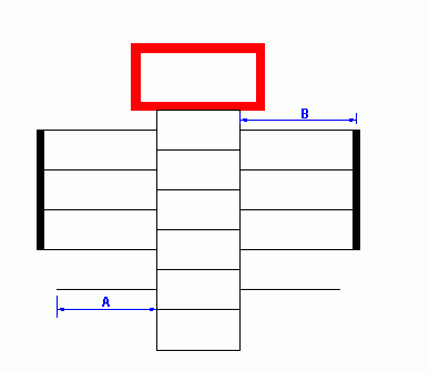 |
| A Wire length |
Lets you specify the length A
of the line representing a wire. |
| B Cable core length |
Lets you specify the length B
of the line representing a cable core. |
| Options |
|
| Visualize terminal pins |
Select this option if you want to show the terminal
pins like in the terminal strip editor. |
| Line color |
Lets you select the color of the line representing the
terminal pins. |
| Cable core length |
Select this option to group all the cable cores
connected on one terminal and connect only one cable core to the
terminal. |
| C Distance to connection
point |
Lets you enter the distance between the terminal and
the line allowing to group the cable cores. |
Bridges
| Name |
Description |
| General |
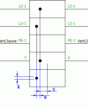 |
| A Dot diameter |
Lets you specify the diameter A
of the dots representing the bridge connection on the terminal. |
| B Bridge offset |
Lets you specify the distance B
between two lines representing a bridge. This adds the parameter to the
Distance before bridge parameter. |
| C Distance before
bridge |
Lets you specify the distance C
between the terminal axis (middle) and the line representing the
bridge. |
| Color |
Lets you specify the color to draw the bridges (point
and line). |
| Automatic bridges |
|
| Color |
Lets you specify the color to draw the automatic
bridges (point and line). |
| Show wire |
Shows or hides the wire connected on the terminal when
you link it with another. |
Cable
A customizable basic symbol (Cable label) represents the cable in the terminal strip
drawing.
The first two zones of the lower part of the dialog box display the text
parameters (such as the font, the color, or the size) as well as their positioning
parameters. Text centers on the intersection point of the rectangle's two diagonals.
The X offset and Y offset parameters allow you to control the distance between the
text and this point.
The third zone of the lower part (Cable label) lets you select a
symbol that is positioned on the base point (the intersection of the rectangle's two
diagonals). Three icons are available to Add
a new symbol, Remove the symbol displayed,
and Edit the symbol displayed.
This symbol is added to the basic symbol. To display your own
symbol, hide the basic symbol by setting its dimensions to 0 and hiding its
text.
| Name |
Description |
| General |
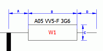
|
| Cable position |
Lets you control the position of the symbol marking
the cable label in relation to the thick line grouping together the
cable cores. The Top parameter corresponds to the first cable core,
the Center parameter positions the symbol in the center of the thick
line and the Bottom parameter places the symbol on the last cable
core.
|
| A Minimum distance before
label |
Defines the length A of the
line separating the rectangle of the cable label and the thick line of
the cable. |
| B Label width |
Defines the width B of the
rectangle of the cable label. |
| C Label height |
Defines the height C of the
rectangle of the cable label. |
| D Maximum distance after
label |
Defines the length D of the
line placed at the other end of the rectangle. |
| Minimum number of cable cores before next
drawing |
Lets you define the number of cable cores on the drawing that
generates an automatic page break.
For example, if you enter 0 in this parameter, if SOLIDWORKS
Electrical cannot place all of this cable's cores on the drawing, it
draws the cable on another.
If you enter 3 in this parameter, SOLIDWORKS Electrical places
three cable cores on this drawing (if it is able to do so, that is,
without exceeding the drawing limit) and draws the other cores on
another drawing. If there is only space to draw two terminals on the
drawing, it places all the cable's cores on a new drawing.
|
| E Distance between
cables |
Lets you define the distance between the two thick lines representing
the cables E.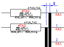 |
| Cable line width |
Lets you define the width of the lines grouping the
cable cores. If you enter 0, it does not apply a
width. |
Destination
This tab lets you manage the display of destinations of cables and
wires.

| Name |
Description |
| General |
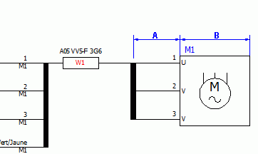 |
| Detail destination component |
When
selected, the drawing represents these destinations by placing one
or more symbols within a rectangle. This details
the arrangement of cable cores and terminal materials for the
component. The drawing also represents wire destinations within a
single rectangle, with successive wires for a unique destination
grouped together. Select an option:
- None. Displays only the mark and location
name.
- For
cables. Displays
a
box containing the destination symbol
information for the cables.
- For
wires. Displays
a
box containing the destination symbol
information for the wires.
- For cables and
wires. Displays
a
box containing the destination symbol
information for the cables and wires.
|
| Destination symbol type |
Specify the type of symbol (Line diagram or Schema) you want to insert.
Options are possible if SOLIDWORKS Electrical does not find symbols of
the requested type. |
| A Destination
line length |
Defines the length A of the line, symbolizing the cable core on the
destination side. This setting also applies to the wire
components. |
| B Length of the rectangle
containing the destination symbol |
Defines the length B of the
side of the rectangle framing the symbol. |
| Symbol centering margin in percent |
Defines the margin between the symbol and its contour,
and assigns a scale factor to the symbol according to its size. |
| A Offset for next
destination |
Defines the offset distance A
when there is a change of location in the cable destination
point. |
Layout
This tab lets you manage the layout of the graphical representation
of the terminal strip within the drawing. The bottom right-hand part of the dialog
box displays one of the following title block styles:
- Default title block: title block associated with the
terminal strip drawings in the electrical project configuration.
- Title block specific to this configuration: generates all
terminal strips with this title block using this configuration.
The bottom left-hand corner of the title block must be
positioned at the coordinates (0,0). All the layout parameters are based on this
point.
| Name |
Description |
| General |
|
| Terminal strip orientation |
Lets you choose whether to draw the terminal strips
vertically or horizontally. |
| Terminal strip mark orientation |
Defines the angle of rotation of the terminal strip
mark placed in the header symbol of the terminal strip. The orientation
of the terminal strip (Horizontal or Vertical) does not assign this
parameter. |
| Terminal mark orientation |
Defines the angle of rotation of the terminal's mark
placed in the terminal symbols. The orientation of the terminal strip
(Horizontal or Vertical) does not assign this parameter. |
| Horizontal
representation |
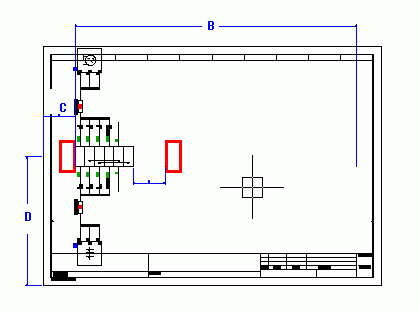 |
| B Terminal strip length |
Defines the maximum length B of
the terminal strip. The origin of this length is the X coordinate of the
right-hand segment making up the rectangle of the header symbol of the
terminal strip. Beyond this limit, it draws the terminals on the
following drawing. |
| C First terminal X
position |
Defines the X coordinate C for
the insertion of the first terminal in relation to the origin (0.0) of
the title block. |
| D First terminal Y
position |
Defines the Y coordinate D for
the insertion of the first terminal in relation to the origin (0.0) of
the title block. |
| Vertical representation |
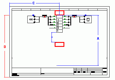 |
| A Terminal strip height |
Defines the maximum height A of
the terminal strip. The origin of this length is the Y coordinate of the
bottom segment making up the rectangle of the header symbol of the
terminal strip. Beyond this limit, it draws the terminals on the
following drawing. |
| C First terminal X
position |
Defines the X coordinate C for
the insertion of the first terminal in relation to the origin (0.0) of
the title block. |
| D First terminal Y
position |
Defines the Y coordinate D for
the insertion of the first terminal in relation to the origin (0.0) of
the title block. |
| Multiple |
|
| Activate |
Activates the graphical representation of several
terminal strips on one drawing. |
| Spacing |
Defines the space between the representation of two
terminal strips. |
| Group |
Lets you specify how to group terminal strips. |
| Sort |
Defines the sort criteria for all terminal strips, or
within a group of terminal strips. |
File Data
This tab lets you define the parameters for the automatic generation
of information to transfer into the properties of the terminal strip drawing. Click
the column to open the Formula management
dialog.
| Name |
Description |
| Description |
Lets you define the parameters for the automatic generation of data to
transfer into the description of the terminal strip drawing. |
| User data/Translatable data |
Lets you specify the parameters for the automatic generation of data to
transfer into the user data of the terminal strip drawing. |