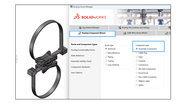
The Routing Component Wizard supports
both
clip
assemblies and clip
parts, allowing you to define and configure assemblies as routing
components. The basic
requirements for both types are the same and the steps to create them in the Routing
Library Manager follow the same process.
Benefits: This update
provides
better flexibility in designing and integrating complex clips into routing workflows.
The
enhancements
in the Routing Library
Manager
are:
- Clip Assemblies: Users can select and configure an assembly file
(.SLDASM) as a routing clip.
- Routing Points: Users can define routing points to align wires,
cables, or
hoses.
- Seamless Integration: Clip assemblies work with existing routing
workflows and are stored in the Routing Library.
Follow
these steps to define a clip assembly in the Routing Library Manager:
- Select the clip assembly.
- Open the Routing Library Manager and navigate to the Routing Component
Wizard.
- Choose
the Route Type and Component
Type,
then click Next.
- Add
route points
(ARPoints) to the clip assembly to
define wire, cable, or hose alignment.
Note: Connection
points
(CPoints) are disabled.
They are not required for clips.
- Add
routing geometry.
- Define the Clip
Axis to specify the routing direction.
- If
the clip assembly requires rotational placement,
add
the Axis of Rotation
.
- Add Mate References
to
define
the
proper
alignment of
the clip
assembly.
- Validate the clip
assembly and
confirm that it meets routing requirements.
- Configure the Design
Table.
- If the clip assembly has multiple configurations, open
the existing Design Table to
make
adjustments.
- If
none exists,
create
a new Design
Table.
- Validate standard and custom entries in the table using
an embedded Excel worksheet.
- Verify Component
Attributes.
Modify
component attributes as required.
- Save the clip assembly.
- Save the configured clip assembly to the Routing
Library.
- Specify a library folder location and filename.
- Save the component as an .XML file.