Description
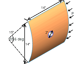
A 16 layered cylindrical composite panel with a symmetric layup [45/-45/90/02/90/-45/45]2 is subjected to axial compressive load of 100 kN. The panel has a circular hole in the center. A pressure of P = 100 kN is applied at the edge shown. The vertical edges are simply supported. The panel is fixed except for axial motion along the edge to which pressure is applied. The edge opposite to where pressure is applied is fixed.
File Name
Browse to
drive letter:\Users\Public\Public
Documents\SOLIDWORKS\SOLIDWORKS
version\samples\Simulation
Examples\Verification\Comp_Buck.SLDPRT and open the
file.
Meshing Parameters
Use a Curvature-based mesher with maximum element size of 5 mm.
Shell Parameters
Symmetric 16 layered composite laminate with all plies made of same material. Each ply is 0.142 mm (0.0056 in) thick.
Material Properties
Linear elastic orthotropic with:
- Elastic moduli. Ex = 135 GPa, Ey = 13 GPa
- Poisson's ratio. νxy = 0.38
- Shear moduli. Gxy = 6.4 GPa, Gyz = 4.3 GPa, Gxz = 6.4 GPa
x direction is along material fiber direction, y direction is along transverse direction in plane and z direction is out of plane. This is different from the global X, Y and Z directions.
Results
| Buckling load (kN) |
Reference |
SOLIDWORKS Simulation |
| Mode 1
|
107 |
107.4 |
| Mode 2 |
109.6 |
109.8 |
| Mode 3 |
116.2 |
113.7 |
| Mode 4 |
140.1 |
140.2 |
| Mode 5 |
151.3 |
167.5 |
Reference
Stanley G.M., "Continuum Based Shell Elements", Ph.D. Dissertation, Department of Mechanical Engineering, Stanford University, 1985.