Description
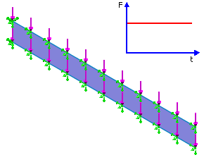
Investigate large displacements of a cantilever beam shown in the figure below. The cantilever beam has a length of 10" and a square cross section of side 1".

File Name
Browse to drive
letter:\Users\Public\Public Documents\SOLIDWORKS\SOLIDWORKS
version\samples\Simulation
Examples\Verification\Nonlinear_Dynamic_1.SLDPRT and open the
file.
Study Type
Nonlinear dynamic.
Shell Parameters
Shell thickness = 1.00" - Thick shell formulation.
Solution Time Increment
8 x 10⁻⁵
Meshing Options
High, Standard.
Meshing Parameters
Use 0.20 in Global Size.
Material Model
Linear elastic isotropic.
Material Properties
Modulus of elasticity = 12000 psi, Poisson's ratio = 0.2, Density = 386.4 x 10⁻⁶ lb/in3.
Restraints and Loads
A fixed restraint is applied to one end of the cantilever. Translation in the normal direction and all rotations are set to zero on the side face of the cantilever.
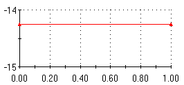
A vertical load of magnitude -14.25 lb is applied suddenly (as shown in the figure) to the top and bottom edges.

Horizontal axis is Time (sec) and vertical axis is Force (lb).
Results
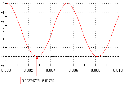
The tip vertical displacement is shown below.

Horizontal axis is Time (sec) and vertical axis is UY Y Displacement (in).
Reference
Bathe K.J., Ozdemir H., Wilson E.L., "Static and Dynamic Geometric and Material Nonlinear Analysis", Report No. UC SESM 74-4, Structural Engineering Laboratory, University of California Berkeley, California, February 1974.