Description
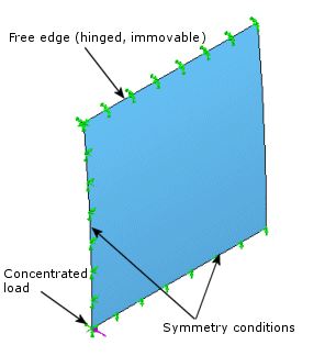
A shallow cylindrical shell is subjected to concentrated load at its center. The curved edges are free and the straight edges are hinged. Due to symmetry, only a quarter of the plate (shown below) is modeled. Determine the deflection.

File Name
Browse to drive
letter:\Users\Public\Public Documents\SOLIDWORKS\SOLIDWORKS
version\samples\Simulation
Examples\Verification\Nonlinear_Static_7.SLDPRT and open the
file.
Shell Parameters
Shell thickness = 12.7 mm - thick shell formulation.
Meshing Parameters
Use a Global Size of 0.8".
Material Model
Linear elastic isotropic.
Material Properties
Modulus of elasticity = 3102.75 N/mm2, Poisson's ratio = 0.3.
Restraints and Loads
The shell is fixed along its straight edges and symmetry conditions are applied to the edges of symmetry. A force is applied at the center as shown:

Results
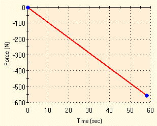
The force versus central deflection curve shown below is in agreement with analytical results.

The results of the nonlinear analysis have been processed by a graphing software to generate the above graph.
Reference
Horrigmoe, G., "Finite Element Instability Analysis of Free-Form Shells," Report
No. 77-1, the Norwegian Institute of Technology, the University of
Trondheim,
Norway (1977).