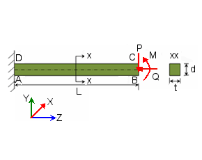
Plot the variation of tip deflections and rotation with applied loads at end BC.

P = 3.844 x 10⁶ Nm, Q = 3.844 x 10³ Nm, M = 0.
Results
-
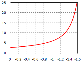
Tip Z displacement variation with applied load P

X-axis shows normalized tip displacement, uz/L. Y-axis shows normalized transverse load, PL2/(EI).
L = 3.2 m, E = 210 x 109 N/m2, I = (1/12) td3= 8.33 x 10⁻⁶ m4.
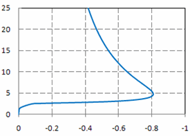
Tip Y displacement variation with applied load P

X-axis shows normalized tip displacement, uy/L. Y-axis shows normalized transverse load, PL2/(EI).
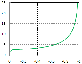
Tip rotation angle variation with applied load P

X-axis shows rotation angle, Θ/(π/2). Y-axis shows normalized transverse load, PL2/(EI).