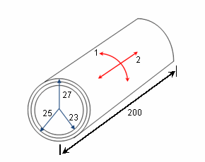
Determine the circumferential stress at different radial locations of a
wrapped thick cylinder subjected to the following loads:
Study A. Uniform internal pressure of 200 MPa (pressure of 100
MPa)
Study B. Uniform internal pressure of 200
MPa and temperature rise of 130 °C
The composite is made of two layers:
an inner isotropic cylinder and an outer orthotropic cylinder. All dimensions are in mm. The
figure is not shown to scale.

In the figure, 1 represents the ply angle
direction and 2 represents the cross ply angle direction for the outer cylinder.
|
File Name
|
Open drive
letter:\Users\Public\Public Documents\SOLIDWORKS\SOLIDWORKS
version\samples\Simulation
Examples\Verification\NAFEMS_R0031-2.SLDPRT.
|
|
Mesh Size
|
Use standard mesh with global element size of 3.76 mm.
|
|
Material Properties
|
Isotropic Inner Layer:
- Elastic modulus: E = 2.1 x 10⁵ MPa
- Poisson's ratio: ν= 0.3
- Coefficient of Thermal Expansion: α = 2.0 x 10⁻⁵/
°C
Orthotropic Outer Layer:
- Elastic moduli: Ex = 130 GPa, Ey = 5 GPa,
Ez = 5 GPa
- Poisson's ratios: νxy = 0.25, νxz = 0.25,
νyz = 0
- Shear Moduli: Gxy = 10 GPa, Gxz = 10 GPa,
Gyz = 5 GPa
- Coefficient of Thermal Expansion: αxx = 3.0 x 10
-6/ °C, αyy = 2.0 x 10⁻⁵/ °C, αzz =
2.0 x 10⁻⁵/ °C
x represents direction 1 in the figure, y represents direction 2
in the figure, and z is along the normal direction to the surface.
|
Results
Obtain the
stress result in MPa at radial locations of the thick cylinder.
Although the stress values show minor variations, they are approximately
the same over the entire surface. Reported results are probed close to the center so there
are no boundary effects.
| Case |
Stress component |
Radial location |
NAFEMS |
SOLIDWORKS Simulation |
| Study A |
SX - Display results in ply
direction on composite surfaces |
Layer 1 - Bottom |
1565 |
1711 |
| Layer 1 - Top |
1430 |
1573 |
| Layer 2 - Bottom |
875 |
894 |
| Layer 2 - Top |
759 |
828 |
| Study B |
SX - Display results in ply
direction on composite surfaces |
Layer 1 - Bottom |
1381 |
1529 |
| Layer 1 - Top |
1260 |
1351 |
| Layer 2 - Bottom |
1096 |
1106 |
| Layer 2 - Top |
936 |
1021 |
Probe the result at locations sufficiently far away from the ends of
the cylinder to avoid boundary effects. Errors in the results are due to the laminated
shell element formulation used to solve the problem.
Reference
NAFEMS, Publication R0031/2, "Composites Benchmarks",
February 1995.