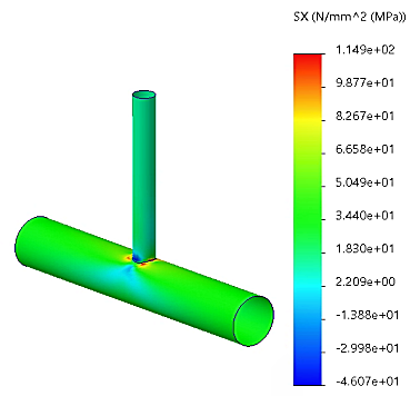
Viewing Stress Results Along Ply Direction To plot stress along the ply direction for the inner face of the cylinder, in the Simulation study tree, right-click the Results folder and click Define Stress Plot . In the Definition tab of the PropertyManager under Display: Select SX: X Normal Stress in Component . Select N/mm^2 (MPa) in Units . Select Bottom in Shell face . Under Composite Options: Set Ply number to 1. Select Display results in ply direction on composite surfaces. Under Deformed shape, select True scale. Click . The stress along the ply direction is shown for the bottom face of the first ply. To plot stress along the ply direction for the outer face of the cylinder: Repeat steps 1-4, select Top in Shell Face , and set Ply number to 8. Click . Parent topic Failure Analysis of a Composite Joint (Simulation Premium only) Previous topic Checking Stacking Direction and Running the Study Next topic Viewing Stress Results Along Transverse Direction