Applying Hydrostatic Pressure

  1. Right-click the External Loads folder of the Partial study and select Pressure pressurevalue.png.
  2. Under Type, select Normal to selected face.
  3. In the graphics area, click the four vertical side faces under the fuel level.
  4. Under Pressure Value:
    1. Select psi in Unit .
    2. Type 1 for Pressure Value .
    3. Select Reverse direction.
  5. Check Nonuniform Distribution.
  6. Select Coordinate System1 (FeatureManager design tree) for Select a Coordinate System coordsys.png.
  7. For Units for x,y, and z select in.
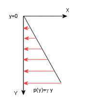
  8. Click Edit Equation. In the equation box type 0.029 * "y" .
    The above options represent the equation F(x,y,z) = 0.029*y, in the cartesian system where the numeric factor represents the specific weight of the fluid. The pressure is normal to the selected faces and starts at zero at the top of the tank and reaches its maximum at its bottom. The pressure distribution can be depicted schematically as follows:
  9. Click PM_OK.gif twice.
  10. Repeat the steps above to apply hydrostatic pressure to the inner bottom face of the tank. Do no select Reverse direction, to apply the correct pressure direction to the bottom face.