Add mates to define relationships between the assembly components.
-
Click Mate
 (Assembly
tab).
(Assembly
tab).
To make selections easier, rotate the view by dragging with
the middle mouse button in the graphics area. Then, after making the
selection, click
Previous View

(Heads-up View toolbar).
Other tools on the Heads-Up View toolbar are
useful as you work through this tutorial. See Zoom, Pan, and Rotate.
-
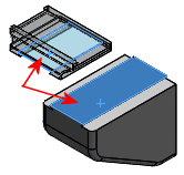
Select the top face of the knee and the bottom face of the
saddle for Entities to Mate
 .
.
The
Mate pop-up toolbar appears in the graphics area.
Coincident

is selected in both the
PropertyManager and the pop-up toolbar. A preview of the coincident mate
appears.
If the Mate pop-up toolbar does not appear, select Show popup dialog under Options in the PropertyManager.
-
To see how you can flip the alignment of the saddle, under
Mate
Type,
for Mate alignment:
-
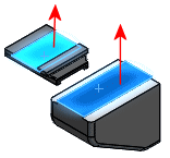
Click Aligned
 .
.
| Vectors normal to the selected faces point in the
same direction. |
 |
-
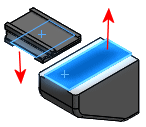
Click Anti-Aligned
 .
.
| Vectors normal to the selected faces point in
opposite directions. |
 |
-
In the PropertyManager, click
 to accept the mate.
The face of the knee and the face of the saddle now lie
in the same infinite plane. The mate appears in the PropertyManager under
Mates.
-
Click again
to close the PropertyManager.