In this topic, you define assembly mating relations between the
components, making the components align and fit together.
-
Click Mate
 (Assembly
tab).
(Assembly
tab).
The Mate
PropertyManager appears.
- In the graphics area, select the top edge of Tutor1, then select the outside edge of the lip on the top of Tutor2.
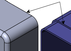
The
Mate pop-up toolbar appears, and the components
move into place, previewing the mate. In the PropertyManager, under
Mate Selections, the edges are
listed in Entities to Mate
 .
.
If the
Mate pop-up toolbar does not appear, select
Show popup dialog under
Options in the
PropertyManager.
- On the Mate pop-up toolbar:
-
Click Coincident
 as the mate type.
- Click
 .
.
A coincident mate appears under
Mates in the PropertyManager.
The
position of Tutor2 is not fully
defined. It has some degrees of freedom to move in directions that are not
constrained by mates.
- Test degrees of freedom by moving the components:
- In the graphics area, select the Tutor2 component and hold down the left mouse button.
-
Drag the component to observe the available degrees of
freedom.