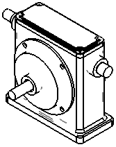
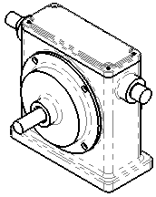
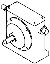
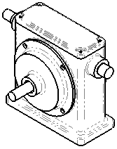
Tangent edges are transition edges between rounded or filleted faces in drawing views in Hidden Lines Removed or Hidden Lines Visible display modes. The most commonly seen tangent edges are the edges of fillets.
Tangent edges are often visible in pictorial (isometric, trimetric, and dimetric) views, but are removed in orthographic (such as front, right, and top) views.
You can also use part configurations to change the display by suppressing fillets.
To specify
the default tangent edge display for all new drawing views, click
and select from the following:
- Visible - a solid line
- Use font - a line in the
default font defined in .
- Removed - not displayed
- Hide ends - hides the
start and end segments of tangent edges
| Visible |
Use font |
 |
 |
| Removed |
Hide ends |
 |
 |
Other options for tangent edge display are in the
Hide/Show Edges PropertyManager.
You can
also
control tangent edge display
as follows:
- Views - to set the
display for an individual view in a drawing, right-click the view in either the
graphics area or the FeatureManager design tree and select Tangent Edge, then choose a tangent edge display
mode.
You can set the color of tangent edges in . In Color scheme settings, select and set the color. The color applies to
only.