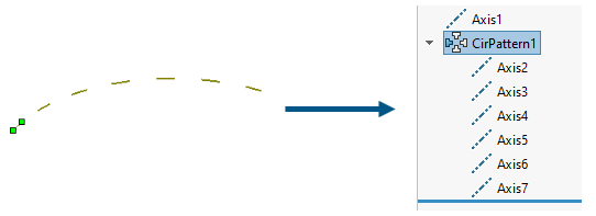
The Circular Pattern PropertyManager
appears when you pattern one or more features around an
axis. You can also pattern
planes and axes.
To open this PropertyManager:
Click Circular Pattern
 (Features toolbar) or .
Some fields that accept numeric input allow you to
create an equation by entering = (equal sign) and selecting global variables,
functions, and file properties from a list.
Direction 1
| |
Pattern
Axis |
Select an entity in the graphics area:
- Axis
- Circular edge
- Linear edge or linear sketch line
- Cylindrical face or surface
- Revolved face or surface
- Angular dimension
The pattern is created around this axis. Click Reverse Direction
 to change the
direction of the circular pattern. to change the
direction of the circular pattern. |
| |
Instance spacing |
Specifies the distance between
the centers of instances. |
| |
Equal
spacing |
Sets Angle
 to 360°. to 360°. |
|
Angle |
Specifies the angle between each
instance. |
 |
Number of Instances |
Specifies the number of instances
of the seed feature. |
Direction 2
| |
Direction 2 |
Enables Direction 2 options. |
| |
Symmetric |
Creates a symmetrical pattern
from the seed feature. |
| |
Instance spacing |
Specifies the distance between
the centers of instances. |
| |
Equal
spacing |
Sets Angle
 to 360°. to 360°. |
|
Angle |
Specifies the angle between each
instance. |
|
Number of Instances |
Specifies the number of instances
of the seed feature. |
Features and Faces
| |
Features and Faces |
Enables Features and Faces options. |
 |
Features to Pattern |
Creates the pattern by using the
selected feature as the seed feature. |

|
Faces
to Pattern |
Creates the pattern by using the
faces that make up the feature. Select all the faces of the feature
in the graphics area. This is useful with models that import only
the faces that make up the feature, and not the feature itself.
When using Faces to Pattern, the pattern must remain
within the same face or boundary. It cannot cross boundaries.
For example, a cut across the entire face or different levels
(such as a raised edge) would create a boundary and separate
faces, preventing the pattern from propagating.
|
Bodies
| |
Bodies |
Enables Bodies options. |
 |
Solid/Surface Bodies to Pattern |
Creates the pattern by using the
bodies that you select in a multibody part. |
Reference Geometry
 |
Reference Plane or Reference Axis to
Pattern
|
Creates the pattern by using the plane or axis
that you select. Limitations:
- If a plane contains a sketch, the plane pattern does not
pattern the sketch.
- A pattern can contain one reference geometry entity
only, either one plane or one axis.
|
Instances to Skip
 |
Instances to Skip |
Skips the pattern instances that
you select in the graphics area when you are creating the pattern.
The pointer changes to  when you hover over each pattern
instance. Click to select a pattern instance. The coordinates of the
pattern instance appear. To restore a pattern instance, click the
instance again. when you hover over each pattern
instance. Click to select a pattern instance. The coordinates of the
pattern instance appear. To restore a pattern instance, click the
instance again. |
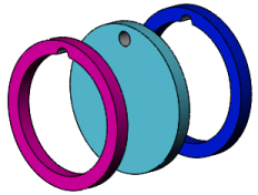
Feature Scope
Apply features to one or more multibody parts by selecting
Geometry pattern under
Options, and using
Feature
Scope to choose which bodies can include the feature.
You must create the model that you want to add the features for
multibody parts before you add those features.
 |
 |
 |
| Cut extrude feature applied to all
multibody parts |
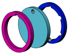
Cut extrude feature using the
circular pattern applied to single body |
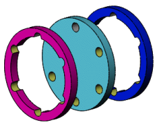
Cut extrude feature using the
circular pattern applied to all bodies |
| |
All
bodies |
Applies the feature to all bodies
every time the feature regenerates. If you add bodies to the model
that are intersected by the feature, these new bodies are
regenerated to include the feature. |
| |
Selected bodies |
Applies the feature to the bodies
that you select. If you add bodies to the model that are intersected
by the feature, you must use Edit
Feature to edit the pattern feature, select those
bodies, and to add them to the list of selected bodies. If you do
not add the new bodies to the list of selected bodies, they remain
intact. |
| |
Auto-select (Available if you click Selected bodies) |
When you create a model with
multibody parts, the feature automatically processes all the
relevant intersecting parts. Auto-select is faster than All bodies because it processes
only the bodies on the initial list and does not regenerate the
entire model. If you click Selected
bodies and clear Auto-select, you must select the bodies in the
graphics area that you want to include. |
 |
Bodies to Affect (Available if you clear Auto-select) |
Select the bodies to affect in
the graphics area. |
Options
| Vary
sketch |
Allows the pattern to change as
it repeats. |
| Geometry pattern |
Creates the pattern using only
the geometry (faces and edges) of the features, rather than
patterning and solving each instance of the feature. Geometry pattern speeds up the
creation and rebuilding of the pattern. You cannot create geometry
patterns of features that have faces merged with the rest of the
part. |
| Propagate visual properties |
Propagates SOLIDWORKS colors,
textures, and cosmetic thread data to all pattern instances.
|
| Full
preview |
Displays a preview of the
computed geometry at each pattern instance location that includes
the start and end conditions. |
| Partial preview |
Displays a preview of the seed
feature geometry at each pattern instance location. |
Instances to Vary
This option is available only when you select a feature for the
pattern instance.
Direction 1 Increments
 |
Spacing Increment |
Cumulatively increments the
spacing between the centers of the pattern instances. For example, if the spacing between instances
in the pattern is 1.5mm,
and you enter .3mm for
Spacing Increment,
then the second instance is positioned 1.8mm from the first, the third
instance is positioned 2.1mm from the second, the fourth instance is
positioned 2.4mm from
the third, and so forth.
 |
| |
Choose Feature dimensions to vary in Direction
1 |
Displays dimensions of the seed
feature in a table. In the graphics area, click the dimensions of
the seed feature to display and populate the table. Adding a value
in the Increment column can
increase or decrease the size and shape of the feature dimension.
|
Modified Instances
 |
Lists the individual instances
that have been modified. To modify an individual
instance, left-click the instance marker in the graphics area,
select Modify Instance.
You can enter values to override the spacing and dimensions in
the callout.
To remove a modified
instance, right-click the instance in the box and click
Delete. You can
remove all modified instances by right-clicking in the box and
clicking Clear
All.
|