You can define a cable
connector between solid surfaces, circular shell edges, or vertices (either of solids or
shells), or a combination of vertices to faces, or vertices to circular edges, or circular
edges to faces.
You can use cable connectors to model the behavior of a cable that connects the
following geometric entities:
Circular
or Planar Faces
When defining a cable connector, you can select either
planar
or cylindrical faces as supports. You can also select split faces as supports. The
selection of split faces allow you to define the cable's connection areas without
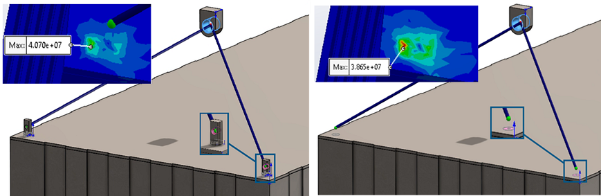
including the physical models of gusset plates or anchor boxes. For example, as
shown in the image below, instead of modeling a hook or a bracket to attach a cable,
you can create a split face where the hook or bracket would attach to the component.
Then, you can use the split face as the support and an offset distance to position
the end joint of the connector. Face selection applies only to solid bodies.
When you select a planar face, the connector places a reference node at the
centroid of the face and uses the direction normal to the face to define
the
axial direction of the cable. For
cylindrical faces, it places a reference node at the centroid of the circular face
and aligns the axial direction along the cylinder's axis. You can define an offset
to move the reference node along the normal or axial direction of the cable
connector. The cable follows a straight path between the two reference nodes
positioned
at the ends. If the selected faces are
concentric, the cable's axial direction aligns with the common axis.
If you select multiple cylindrical faces at one end, they must be concentric. The
cable connector uses distributed coupling to connect each reference node to the
coupling
nodes of the selected face.
Edges
You can define a cable connector between the circular edges of shell bodies.
For circular edges, the connector places the reference node at the centroid of the
circular edge, similar to cylindrical faces. You can specify an offset to move the
reference node along the axis of the circular edge.
The cable follows a straight path between the two reference nodes. You can use
edges as support at one end and select faces or vertices for the other end. If you
select multiple circular edges at one end, they must be concentric.
Vertices
You can define a cable connector between the vertices of solid or shell
bodies. The connector places the reference node directly at the selected vertex. It
connects the reference node to the coupling nodes positioned within a small area of
influence using distributed coupling. Unlike the selection of edges or faces, the
enforcement of coupling formulation does not spread across a face or along an edge,
but it applies locally around the area of influence of the vertex.
You can select a vertex at one or both ends of the cable, or select a vertex
at one end and a face or an edge at the other end. The cable always forms a straight
connection between the two reference nodes.