View Palette
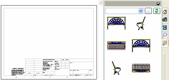
Use the View Palette  , located in the Task
Pane, to quickly insert one or more predefined views to the drawing.
It contains images of standard views, annotation views, section views,
and flat patterns (sheet metal parts) of the selected model. You can drag
views onto the drawing sheet to create a drawing view. Each view is created
as a model
view.
The palette view orientations
are based on the eight standard orientations (*Front,
*Right, *Top,
*Back, *Left,
*Bottom, *Current,
and *Isometric) and any custom
views in the part or assembly. After you place the view, you can fold
or project
views from it.
When you use a view, it is removed
from the palette.

The View Palette populates when you:
 The View Palette supports AutoCAD®
2002 through 2008.
To insert drawing views from the View Palette:
In a drawing with no parts or assemblies open:
Select the Task Pane and the View Palette  .
.
Click Browse
 in the View Palette.
Browse to a part or assembly, then click Open.
Drag a view into the graphics area.
You can align additional views to existing ones using the dotted reference
lines that appear between them if Auto-start
projected view is selected.
In a drawing with parts or assemblies open:
Select the Task Pane and the View Palette  .
.
Select the part or assembly that you want to insert
from the list in the upper left corner of the View Palette.
Drag a view into the graphics area.
You can align additional views to existing ones using the dotted reference
lines that appear between them if Auto-start
projected view is selected.
 If you delete a view from a drawing, you
can re-insert the view from the View Palette by clicking Refresh
 at the top of the palette.
To clear the View Palette after deleting views:
If you delete all views in the View
Palette, click Clear All  in the View Palette
to remove external references from a drawing.