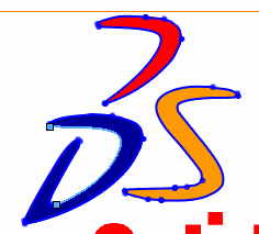
Sketch Picture
Sketch Picture includes the following capabilities:
-
Insert pictures (.bmp, .gif, .jpg, .jpeg, .tif, .tiff, .wmf, .png, .psd) on a sketch plane.
-
Use pictures as an underlay for creating 2D sketches.
-
Convert raster data to vector data.
If you insert a sketch picture of a .tiff file, the resolution is limited to 4096 x 4096. Files that exceed this limit are cut in half until both dimensions meet the limit. For example, if you insert a .tiff file that is 5000 x 3000, the file is reduced to 2500 x 1500.
Recommendations for Auto Trace
-
Source image should be hi-resolution, with a minimum of 300dpi.
-
Line art should be pen on paper, with precise contours and high contrast.
-
Colors should be as uniform as possible within the area you select.
Compatibility with Auto Trace
-
You can use still image formats such as .bmp, .gif, or .jpg, but not animated formats such as animated .gif or .avi files.
-
You can apply Auto Trace to part or assembly files (*.sldprt and *.sldasm), but not to drawing files (*.slddrw).
Insert Picture
The first page of Sketch Picture PropertyManager controls the picture's position, size, angle, orientation, aspect ratio setting, and transparency.
-
You insert the picture with its (0, 0) coordinate at the sketch origin, an initial size of 1 pixel per 1 mm, and locked aspect ratio.
-
Pictures are embedded in the document (not linked). If you change the original image, the sketch picture does not update.
-
If you sketch on top of the picture, there is no snap to picture, inferencing, or auto tracing capability. If the image is moved, or deleted and replaced, the sketch does not update.
-
If you hide the sketch, the picture is also hidden.
-
Pictures can be inserted into assemblies when editing a part in context, but they cannot be inserted into assembly sketches.
Create Auto Trace
The second page of the Sketch Picture PropertyManager enables you to trace outlines or select areas by color to create vector data. This creates a sketch that you can save and edit as needed. Some uses include converting:
The second page of the Sketch Picture PropertyManager is only available as an add-in. Click Tools, Add-Ins, then select Autotrace in the dialog box.
To insert a picture on a sketch plane:
-
In an open sketch, click Sketch Picture  (Sketch toolbar) or click Tools, Sketch Tools, Sketch Picture.
-
In the dialog box, browse to the picture file and click Open.
The picture is inserted.
-
Set the properties on the first page of the Sketch Picture PropertyManager as necessary.
 You can resize the picture in the graphics area by dragging its handles. You can drag the picture without changing its size when the pointer changes to
  .
.
-
Click  .
.
To edit the picture:
 If you are on the second page of the Sketch Picture PropertyManager, click
  .
.
Double-click the picture and edit the values in the PropertyManager.
To delete the picture:
Double-click the picture and press Delete.
To covert the picture to vector data:
-
Follow steps 1 through 3 from To insert a picture on a sketch plane.
-
Click  to display the second page of the Sketch Picture PropertyManager.
-
Under Trace Settings:
-
Select a tool for Image Type.
-
Select a tool for Selection tools, and create a border around the image you want to trace.
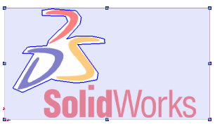
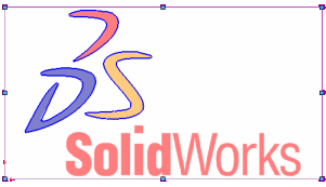
-
Under Preview Settings, clear or select Show source image and Show traced geometry to isolate and verify source and trace images.
-
Under Begin Trace, adjust the sliders.
|
 Note the following: Note the following:
-
Sliders control the source image.
-
Sliders for Color tolerance and Recognition tolerance are dynamic.
-
Set Color tolerance towards the left to increase color precision, and decrease color deviation.
-
Set Recognition tolerance towards the left to increase the precision with which the trace follows the source geometry.
|
-
-
Click Apply.
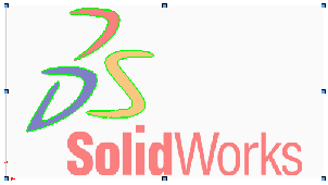
 You can clear Show source image so that only the vector sketch elements display when you create the sketch.
-
Click  to create the sketch.
-
Select individual spline segments and adjust their shape as required.
