DimXpert Show Tolerance Status
The DimXpert Show Tolerance Status  tool identifies the
manufacturing features
that are fully constrained, under constrained, and over constrained from, primarily, a dimensioning and tolerancing perspective. However, certain geometric relationships between features and the orientation of each feature relative to the annotation views are also considered.
To show the DimXpert tolerance status of a part:
-
Use DimXpert to add dimensions and tolerances to a part.
-
Click Show Tolerance Status  (DimXpert toolbar) or Tools, DimXpert, Show Tolerance Status.
DimXpert displays feature faces in default colors representing one of the three states:
|

|
-
Faces with no constraint color are not associated to a DimXpert feature, dimension, or tolerance.
-
Set the tolerance status color at Tools, Options, System Options, Colors, DimXpert (Under, Fully, or Over Constrained).
|
|
In the DimXpertManager:
-
Features with no mark after the name are fully constrained.
-
Features with (+) following the name are over constrained.
-
Features with (-) following the name are under constrained.
|

|
-
To exit tolerance status mode, click Show Tolerance Status  or another SolidWorks command.
Examples
These examples illustrate the effect that dimensions and tolerances have on tolerance status.
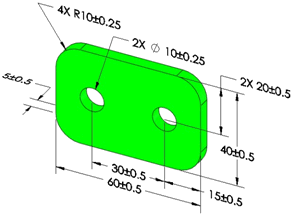
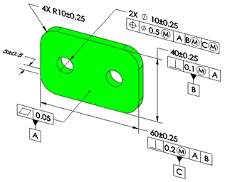
Fully Constrained
Plus and minus dimensions
|
|
|
|
|
|
Geometric tolerances
|
|
|
|
|
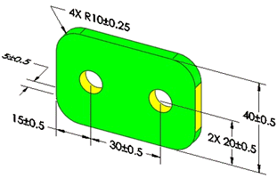
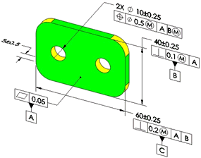
Under Constrained
|
|
|
In this example, a size tolerance is missing from the two-hole pattern and the right hand plane is not dimensioned or toleranced.
|
|
|
|
|
|
In this example, the holes are not located along the horizontal direction, and a size tolerance is missing from the corner fillets.
|
|
|
|
|
Over Constrained
|
|
|
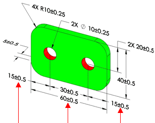
The hole pattern is located from the left and right hand planes and there is a dimension applied between the left and right hand planes.
Removing any of the four dimensions applied to the four features would resolve the over constrained condition.
|
|
About Plus and Minus Tolerancing
When using only plus and minus tolerancing schemes (no geometric tolerances), there are several cases that prevent a part from being fully constrained. The most common cases are when you create features on common centerlines and axes, meaning that the distance between features is zero.
Examples
|
|
|
|
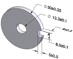
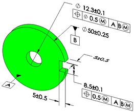
In this part, there are no dimensions or tolerances controlling the coaxiality of the 12.3 and 50 diameters, and no dimensions or tolerances controlling the vertical offset between the 12.3 diameter hole and 8.5 wide notch.
|
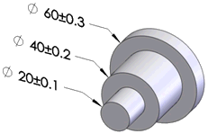
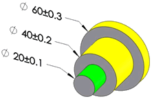
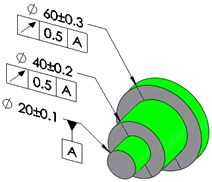
In this part, there are no dimensions or tolerances controlling the coaxiality of the three diameters.
|
|
|
|
|
|
|
|
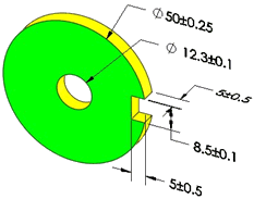
When you click Show Tolerance Status  , several features are under constrained (in yellow). , several features are under constrained (in yellow).
|
|
|
|
|
|
|
|
If you apply these tolerances schemes, all features are fully constrained.
|
Implied Constraints
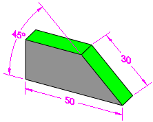
DimXpert for parts recognizes a feature's implied vertical and horizontal constraints when checking its tolerance status.
Example
|
|
|
The top plane is fully constrained by an intersect line and a horizontal constraint.
|
Tangency Constraints
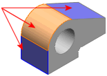
DimXpert for parts considers the effects tangencies between planes and cylinders have on dimensioning, tolerances, and constraint status. All DimXpert for parts functions support and consider tangency constraints.
|
Tangency constraints exist where a plane and cylinder are adjacent.
|
|

|
|
|
Cylinder type features include boss, cylinder, and simple hole.
|
The angled plane and adjacent tangent cylinders are fully constrained.
|
The Tangency annotation type appears in the DimXpertManager under the toleranced feature. Tangency annotation types have an origin feature and a tolerance feature.

 Tangency constraints are supported for pocket features. They are not created for fillet, notch, or slot features, which have a built-in implied tangency.