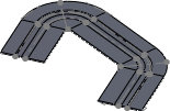
The Swept Flange PropertyManager creates compound bends in sheet metal parts.
To display this PropertyManager:
Open a part that has an open profile sketch as the profile, and a sketch or a series of existing sheet metal edges as the path.
Profile and Path
 |
Profile |
Sets the open, non-intersecting profile sketch used to create the sweep. Select the profile sketch in the graphics area or FeatureManager design tree. |
  |
Path |
Sets the path along which the profile sweeps. You can select a sketch or a series of existing sheet metal edges for the path. Select the path sketch in the graphics area or FeatureManager design tree. Select the path edges in the graphics area. Path requirements:
- The path can be open or closed, and can be a set of sketched curves contained in one sketch, a curve, or a set of model edges. If the path is a sketch, it must be an open profile. If the path is a selection of adjoining edges, the path can be a closed profile.
- The start point of the path must lie on the plane of the profile.
- A set of sketched curves (lines and arcs) must meet at end points (C0 - positional continuity). Any sharp corner is automatically filleted with appropriate radii. There are two different radii on each side of the path to create the swept flange. The filleting will fail if a fillet cannot be made for the round corner, usually because the edges to be filleted are too short. In this case, the swept flange will fail.
- No additional filleting is created for a round corner, even if the radius of the round corner is smaller than the necessary radius to create the swept flange. If the radius of the round corner is too small, the swept flange will fail.
|
| |
Flatten along path |
When selected, the profile is flattened. Then, the profile is rotated parallel to the plane of the path, but the path is not flattened. The result is a flat pattern shape similar to the shape of the path.
When you select Flatten along path, you can also select Material inside. Depending on the geometry, the flat pattern may only succeed when Material inside is selected or cleared. The flat pattern may fail for either choice of Material inside because of self-intersecting geometry on flattening.
When cleared, in flat patterns, the profile is flattened. Then, the profile is rotated perpendicular to the plane of the path. The path is flattened and the result is a rectangular shape.
 |
 |
| Selected |
Cleared |
For flat patterns, the software calculates a linear calculation. Compression and stretching of the material are not taken into account.
|
Sheet Metal Gauges
| |
Use gauge table |
Lets you select a gauge table as the base of the swept flange. The sheet metal parameters (material thickness, bend radius, and bend allowance) use the values stored in the gauge table unless you override them. |
 |
Select Table |
Lets you select or browse to a gauge table. This list is populated if you set the folder to search for gauge tables in. In Show folders for, select Sheet Metal Gauge Table. |
Sheet Metal Parameters
 |
Thickness |
Sets the material thickness. |
| |
Reverse direction |
Changes the direction in which the sheet thickness is applied. |
 |
Bend Radius |
|
Bend Allowance
| Bend Allowance Type |
Lets you set a different value from the default bend allowance. |
Auto Relief
| Relief Type |
Sets the type of relief cut to be added: Rectangular, Tear, or Obround. |
| Use relief ratio |
If Relief Type is Rectangular or Obround and you select Use relief ratio, set a value for Ratio. If you clear Use relief ratio, set values for Relief Width  and Relief Depth and Relief Depth  . . |