Fill Surface PropertyManager

Set the PropertyManager options based on the type of filled surface you want to create.

To open the Fill Surface PropertyManager:

Click Filled Surface on the Surfaces toolbar, or click Insert > Surface > Fill.

Patch Boundary

Patch Boundary Defines the edges of the patch you apply. Boundaries include the following properties and capabilities.
  • You can use surfaces or solid edges, as well as 2D or 3D sketches as boundaries for the patch. Composite curves are also supported.
  • For all sketch boundaries, you can select only a Contact patch as the type of Curvature Control.
  Alternate Face With Alternate Face, you can flip the boundary face for the curvature control of the patch. Alternate Face is used only when creating a patch on a solid model.
 

Example of a solid model, using Contact as the Curvature Control. The filled surface feature automatically selects a direction when you pick a boundary. In some cases, there is more than one possible direction option. To choose other directions, select Alternate Face.

  Curvature Control

You can apply different types of Curvature Control in the same patch.

Example: Multiple Curvature Control

Curvature Control defines the type of control you want to exert on the patch you create. Select one of the following:

Contact

Creates a surface within the selected boundary.

Tangent

Creates a surface within the selected boundary, but maintains the tangency of the patch edges.

Curvature

Creates a surface that matches the curvature of the selected surface across the boundary edge with the adjacent surface.

  Apply to all edges The Apply to all edges check box enables you to apply the same curvature control to all edges. If you select the function after applying both Contact and Tangent to different edges, it applies the current selection to all edges.
  Optimize surface Select the Optimize surface option with two or four-sided surfaces. The Optimize surface option applies a simplified surface patch that is similar to a lofted surface. Potential advantages of the optimized surface patch include faster build times, and increased stability when used in conjunction with other features in the model.
  Show preview Display a shaded preview of the surface fill.
  Reverse Surface Change the direction of the surface patch. The Reverse Surface button is dynamic, and only displays when all these conditions are met:
  • All boundary curves are coplanar
  • No constraint points exist
  • No interior constraints
  • Filled surface is non-planar
  • You select Tangent or Curvature for Curvature Control
 

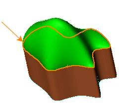
Example of Surface Fill with Reverse Surface
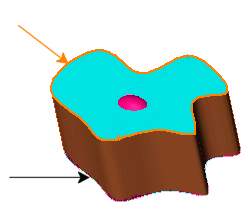
You select the top profile for the tangent surface fill (orange arrow), but the surface is attached to the bottom profile (black arrow).

Correction is required.

The red section is the top of the fill surface extruding from the bottom profile through the top (blue).

You select the top profile for the tangent surface fill (orange arrow), and click Reverse Surface.

Correction is applied.

The tangent fill surface (green), is correctly attached to the top profile.

Constraint Curves

Constraint Curves surface_constraint_curve.png allow you to add slope control to the patch. They are used primarily with industrial design applications. You can create a constraint curve using sketch elements such as sketch points or splines.

Example: Imported Surface

Example: Industrial Design

Resolution Control

If your filled surface is not smooth, you can improve its quality by adjusting the Resolution Control surface_mesh.png slider.
The Resolution Control is available only when the Optimize Surface check box is cleared.
The resolution is set to 1 by default. Change the setting to 2 or 3 to increase the number of patches defining the surface. A higher setting improves the quality of the surface profile.
Changing the resolution increases the model size and processing time. You should not change the default setting if your surface is satisfactory.
Quality set to 1 Quality set to 2

Options

You can create a solid model with the Filled Surface tool.

Fix up boundary Constructs a valid boundary by automatically building missing pieces or trimming pieces that are too big.
Surface fill (red) is created despite the gap in the boundary. The gap between the blue and orange surfaces is bridged by extending the curve internally to the orange surface. Surface fill (red) is created despite the green boundary being larger than the sides of the fill patch. To create the surface fill, the edges are split internally.
Merge result The behavior for this option depends on the boundaries. When all the boundaries belong to the same solid body, you can use the surface fill to patch the solid. If at least one of the edges is an open sheet edge and you select Merge result, then the Surface Fill knits with the surfaces to which the edges belong. If all the boundary entities are open edges, then a solid may optionally be created. Merge result option allows:
  • Streamline operation, eliminating Replace face.
  • Hide solid details within the model.
Model without Filled Surface applied. Note the features inside. Model with Filled Surface applied and Merge result selected. The surface fill joins the solid, removing the features inside.
   
Model with Filled Surface applied and Merge result cleared. The surface fill creates a new surface, and the features inside remain.
Create solid Forming a solid is possible if all the boundary entities are open surface edges. The option Create solid is cleared by default.
Reverse direction When patching a solid with a filled surface there are often two possible results. Click Reverse direction to correct if the filled surface displays in an unwanted direction.

Curvature Display

Mesh preview Applies a preview mesh on the selected faces to better visualize the surfaces.
Mesh density Available when you select Mesh preview.

Adjusts the number of lines of the mesh.

Zebra stripes Displays zebra stripes, to make it easier to see surface wrinkles or defects.
Curvature combs Activates the display of curvature combs.

Select at least one of these options:

Direction 1

Toggle the display of curvature combs along Direction 1.

Direction 2

Toggle the display of curvature combs along Direction 2.

For either direction, select Edit Color to modify the comb color.

Scale Available when you select Curvature combs.

Adjusts the size of the curvature combs.

Density Available when you select Curvature combs.

Adjusts the number of lines of the curvature combs display.