With the Advanced Hole tool, you can define advanced holes
from the near and far side faces. Hole element flyouts help guide the process.
To open this PropertyManager:
- Click Advanced Hole
 (Features toolbar) or .
Type Tab Options
Specify these options on the Type
 tab.
tab.
Hole Callout
You can customize hole callouts that match the order and variables required for manufacturing, then use the callouts in manufacturing drawings.
| Default callout |
Removes all customizations you made to all hole callouts in the PropertyManager. |
| Customize callout |
To customize a callout string, double-click it in the Callout String list and select variables. You can also select Callout Variables to display a list of all variables. Modified strings are marked with an asterisk in the list. To reorder the callouts, select the Callout String and click Move Up and Move Down.
To restore the default options for individual Callout String items, right-click a string and click Restore Default String.
|
Near And Far Side Faces
 |
Select one or more faces or planes to sketch on
|
Displays a temporary preview of the hole on the selected plane or face. The preview does not determine the hole position. Use the Positions tab to position the holes. |
| |
Far Side
|
Select a face or plane. Available when you select one
or no items. Activates the Far Side values in
the element flyout. Use the flyout to add or delete elements. Define
element values under Element
Specification. |
| |
Use baseline
dimensions |
Measures near and far side elements from the same
initial baseline dimension. This option also specifies the end
condition automatically to Offset from
Surface for each element in the hole stack. Other options related to using baseline
dimensions include:
- For a counterbore, countersink, or taper
threaded element, you can select Use standard
depth to ensure that the depth of the
element is the same depth defined in the Hole Wizard
data table.
- For a straight threaded element, you can
select a formula from a list to calculate its
depth.
|
Element Specification
The options available and their icons vary depending on the advanced hole type
selected in the element flyout and the values defined within this Element
Specification section.
| |
Standard
|
|
| |
Type
|
|
| |
Size
|
|
| |
Custom sizing
|
Click the icons to toggle the override options on and off. You can customize the diameter, end condition, and depth. End Condition. Select one of the following:
|
Blind
|
|
|
Through All
|
|
|
Up To Next
|
|
|
Up To Next Element
|
Available from Near Side only, Far Side only, or from both sides. Available for the last element in the Near Side flyout if Far Side is selected. Extends this element to the nearest face of the first element in the Far Side flyout.
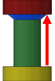
| The last element from the Near Side (blue) is set to Blind. The first element from the Far Side (green) is set to Up To Next Element. The depth of the green element is defined from the end of the yellow element till it meets the blue element, in the direction shown by the arrow. The depth of the green element adjusts to remain in contact with the yellow and blue elements. |
|
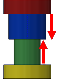
| The last element from the Near Side (blue) and the first element from the Far Side (green) are both set to Up To Next Element. The depth of each element is the total distance between the red and yellow elements divided by two. The depth of both elements adjusts to remain in contact with the yellow and red elements. |
|
|
|
Offset From Surface
|
|
|
Up To Selection
|
Select an entity:
- Sketch or reference point
- Vertex
- Sketch line, model edge, or axis perpendicular to the central axis of the hole
- Planar face, surface, or reference plane that is not parallel to the central axis of the hole
- Nonplanar face or surface that intersects the central axis of the hole
|
|