Modeling is improved for baffles and bubblers that are part of
cooling system components.
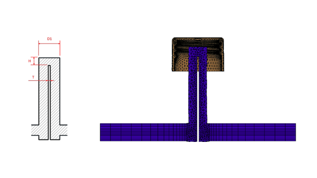
For baffle cooling components, a blade inserted
in a channel splits the flow passage. To accurately model the flow passage through a
baffle cooling component, specify the diameter (D1), the blade thickness (T), and tip
height (H). Previously, only the diameter (D1) of the baffle was required. The image
shows a cross-section of a baffle design (left side) and the hexahedral mesh of a baffle
cross-section (right side).
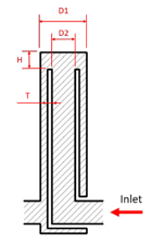
For bubblers, an inner tube replaces the
blade. To accurately model a bubbler cooling component, specify the outer (D1) and inner
tube diameters (D2), the tube thickness (T), and the tip height (H). Previously, only
the outer (D1) and inner tube diameters (D2) were required.
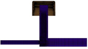
The enhanced modeling of the baffle and
bubbler flow channel enables the creation of an accurate hexahedral mesh across the
cross section. This more-accurate mesh representation improves the overall accuracy of
the coolant flow and the mold cooling solutions.
 |
 |
| Bubbler cross-section (2021) |
Hexahedral mesh of a bubbler cross-section
(2021) |