|
N/A
|
- Name
Specifies the actor name. This name appears in the Collaboration or Assembly tree and is the default tooltip text.
|
all
|
- Tooltip
Specifies the tooltip text that appears when you hover over the actor. The default is the actor name, but you can select a different property or meta-property, or type a text string. To type text, which itself can contain properties, select
String and use the
Tooltip string property.
Note:
By default, labels attached to an actor display the actor's tooltip text. To change this behavior, modify the label's
Text property.
|
all
|
- Tooltip string
(Available when
Tooltip is
String.) Specifies the tooltip text. Type your text, optionally with
property keywords. For geometry actors, click
 to display the
Text pane, where you can type multiple lines of text and more easily embed properties. to display the
Text pane, where you can type multiple lines of text and more easily embed properties.
See Text pane for details on property keywords and the Text pane.
|
all
|
- Opacity
Specifies the opacity, from 0 (transparent) to 255 (solid).
|
all
|
- Stay on top
Makes the collaborative actor visible even when a geometry actor covers it.
 |
 |
| Disabled
|
Enabled
|
|
all
|
- Auto show
Displays hidden annotation and measurement actors temporarily when you move the mouse pointer over the associated geometry actor. The annotation or measurement disappears when you hover over a different actor. Note:
The Collaboration tree does not reflect this temporary change of visibility.
|
all
|
- Auto alignment
-
Specifies positions for collaborative actors with respect to their
associated geometry actors:
Perimetric,
Circle,
Rectangle,
Bottom,
Bottom and left,
Bottom and right,
Bottom and top,
Top,
Top and left,
Top and right,
Left,
Left and right,
Right,
Free 2D,
Free 3D.
Notes:
- To align collaborative actors using magnetic lines,
Auto alignment must be
Free 2D or
Free 3D. When dragged onto a magnetic line, an
actor's
Auto alignment is set to
Free 2D automatically.
- To ensure that cutting planes are applied to annotations, you must
set
Auto alignment to either
Free 2D or to
Free 3D.
|
all
|
- Auto hide
Specifies whether the annotation should be hidden if the anchor of the label or callout is hidden.
|
all
|
- Draw style
(Available with
is not
None.) Specifies how annotations connect to their associated actors: -
Attach lines - Draws a line to each actor.
-
Bounding box - Draws one line to a bounding box around the actors.
 |
 |
| Attach lines |
Bounding box |
|
all
|
- Show inertia axes
Displays axis lines at each attach point to show actor orientation in the world coordinate system.
|


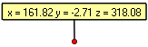
|
- Column format
Lists the x, y, and z coordinates vertically. To list the coordinates horizontally on one line, clear this property.
|

|
| Disabled
|
Enabled
|
|

|
| Text
|
- Color
Specifies the text color.
|
all
|
- Font
Specifies the font family, style, and size of actor text. The default font family is your machine's default font or Arial depending on
Use default GUI font for text (Application Preferences - Viewport). The default size is specified by
Font size ([Default] Document Properties - Paper Space).
Notes:
-
Font (size) and
Size properties are linked.
- When a font is not available in a vector image format, it is replaced by a default font. If the vector output is not acceptable, use a different font in Composer.
|
all
|
- Size
Specifies the text size, in points. The default size is specified by
Font size (in [Default] Document Properties - Paper Space).
Notes:
-
Font (size) and
Size properties are linked.
- Because
Size is stored as pixels in Composer files, changing your screen resolution (DPI) changes rendered text sizes.
|
all
|
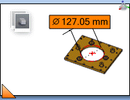
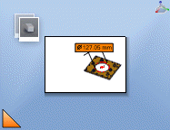
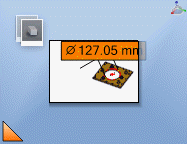
- Size in paper space
Defines the font size in the paper space. When you resize the viewport or zoom the paper space, the text scales accordingly. To define text size as fixed in the viewport, clear this property.
 |
| Before Zooming the Paper Space
|
 |
| After:
Size in paper space Enabled |
 |
| After:
Size in paper space Disabled |
Note:
You can specify the default value using
AnnotationRelativeComposer (for Composer) or
AnnotationRelativePlayer (for Composer Player) on the Application Preferences - Advanced Settings page.
|
all
|
- Parent (level)
Specifies the actor whose
Text value is used as the annotation text. You can choose the selected actor (level 0) or any parent. For example, you can select a part or its parent assembly.
|

|
- Text
Specifies which property or meta-property is displayed as the actor's text. - For annotations other than coordinate labels: To type text, which itself can contain properties, select
String and use the
Text string property.*
- For coordinate labels: By default, this property is set to
None. In this case, only the coordinates are displayed.
|
|
- Text string
(Available when
Text is
String.) Specifies the text. To type multiple lines of text or to embed properties, click
to display the
Text pane. See Text pane.
|
|
- Wrap
Wraps text. Selecting this option displays an anchor at the top right-hand corner of the annotation. Drag the anchor horizontally to change the width of the label, or specify it in the
Wrap width field.
|
|
- Wrap width
(Available when
Wrap is enabled.)
Specifies the width of the annotation, in millimeters.
|
|
| Callout exponent
|
- Quantity exponent
Specifies the location of the BOM quantity on the callout:
-
None (no exponent)
-
Top-right
-
Bottom-right
-
Top-left
-
Bottom-left
Note:
To display quantities of 1, enable
ShowCalloutExponentX1 (Document Properties - Advanced Properties page).
Example: Top-right exponent with font ratio of 75%:

|
|
- Font ratio
Specifies the size of the
Quantity exponent text as a percentage of the callout text.
|
|
- Exponent Shape
- (Available when
Quantity exponent is enabled.)
Displays the quantity exponent with a circular background of the same color as
the callout background.
|
|
| Attach
|
- Type
-
Specifies the attachment line style. You can position the attach line by
dragging the anchor at either endpoint.

|
None(no line to the attach point)
|

|
Model
|

|
Vertex
|

|
Gradient tooltip
|

|
Tooltip style
|

|
Line
|

|
User(three anchors)
|

|
Simple
|

|
Arc tooltip
|

|
Basic
|
Note:
If you select None as the attach type for labels and
callouts, the attachment line will disappear. However, if you drag the attach
anchor, the attachment line will reappear. To prevent this from happening, you
can subscribe the annotation to a style. See
Apply a Style.
|
all
|
- Width
(Available when
Attach
Type is
Line,
Vertex,
Model,
Simple,
User, or
Arc tooltip.) Specifies the width of the attach line, in millimeters.
|
|
- Color
(Available when
Attach
Type is
Line,
Vertex,
Model,
Simple, or
User.) Specifies the attach color.
|
|
- Line Type
(Available when
Attach
Type is
Line,
Vertex,
Model,
Simple, or
User.) Specifies the attach line type.
|
|
- End
(Available when
Attach Type is
Line,
User, or
Simple.) Specifies the attach extremity symbol.
 |
None |
 |
Bold arrow |
 |
Medium arrow |
 |
Thin arrow |
 |
Rhombus |
 |
Round |
 |
Cross |
|
|
- Size
Specifies the size of the extremity, in millimeters.
|
|
- Curvature
(Available for
Arc tooltip only.) Specifies the arc shape. For 2D panels only, you can change the curvature by dragging the curvature anchor in the viewport.
|
|
| Attach border
|
- Show
Displays an attach border. Not available for all attach types.
|
|
| Without attach border |
With attach border (pink) |
Note:
For annotations,
Border settings override
Attach border settings.
|
|
- Color
Specifies the attach border color.
|
|
- Opacity
Specifies the border opacity, between 0 (transparent) and 255 (solid).
|
|
- Type
Specifies the border line type.
|
|
- Width
Specifies the attach border width, in millimeters.
|
|
| Shape
|
- Shape
-
Specifies the annotation or label shape.

|
None
|

|
Rectangle
|

|
Rounded Rectangle
|

|
Square
|

|
Circle
|

|
Ellipse
|

|
Rhombus
|
-
Note:
When the label orientation is set to
Auto, if a measurement value overlaps the leader
line and you set its label's shape to
None, some padding will be applied around the
measurement value to ensure that it remains easy to read.
|
all
|
- Color
Specifies the shape border color.
|
all
|
- Opacity
Specifies the shape border opacity.
|
all
|
| Line
|
- Width
Specifies the line width, in millimeters.
|
all
|
- Opacity
Specifies the actor opacity (between 0 and 255).
|
all
|
- Color
Specifies the line color.
|
all
|
- Type
Specifies the line style.
|
all
|
| Border
|
- Show
Displays the border.
|
all
|
- Width
Specifies the border line width, in millimeters.
|
all
|
- Opacity
Specifies the border opacity (between 0 and 255).
|
all
|
- Color
Specifies the border color.
|
all
|
| Event
|
- Link
Defines the action performed when a user clicks an actor or hotspot in the viewport or in vector image output (see the Technical Illustration - Hotspots tab).
To create an event link: - Click in the
Link field and then click
.
- In the
Select a Link dialog box, select a link type in the
URL field, specify an appropriate target for that type, and then click
OK.
See Select a Link.
- To test the event in the viewport, disable
Design Mode
 (status bar) and then click the actor or hotspot. (status bar) and then click the actor or hotspot.
|
all
|
- Pack linked resource
(Available when the
Link property specifies a
file:// URL.) Includes the linked file as part of the Composer document. To omit the file, clear this property and ensure that recipients of the document have the linked file in the same absolute path.
|
all
|
| Measurement / GD&T
|
- Pre symbol, Middle symbol, Post symbol
Specifies the pre-, middle-, or post-position GD&T symbol.
| |
None |
 |
Straightness |
 |
Flatness |
 |
Circularity |
 |
Cylindricity |
 |
Line Profile |
 |
Surface Profile |
 |
Angularity |
 |
Perpendicularity |
 |
Parallelism |
 |
Position |
 |
Concentricity |
 |
Symmetry |
 |
Circular Runout |
 |
Total Runout |
 |
Projected Tolerance Zone |
 |
Max. Material Condition |
 |
Min. Material Condition |
 |
Free State Variations |
 |
Diameter |
 |
Plus Minus |
 |
Plus |
 |
Minus |
 |
Equal |
 |
To be Defined |
|


|
- Pre string, Middle string, Post string
Specifies the pre-, middle-, or post-position string.
|
|