| N/A |
- Name
Specifies the actor name. This name appears in the Collaboration or Assembly tree and is the default tooltip text.
|
- Tooltip
Specifies the tooltip text that appears when you hover over the actor. The default is the actor name, but you can select a different property or meta-property, or type a text string. To type text, which itself can contain properties, select
String and use the
Tooltip string property.
Note:
By default, labels attached to an actor display the actor's tooltip text. To change this behavior, modify the label's
Text property.
|
- Tooltip string
(Available when
Tooltip is
String.) Specifies the tooltip text. Type your text, optionally with
property keywords. For geometry actors, click
 to display the
Text pane, where you can type multiple lines of text and more easily embed properties. to display the
Text pane, where you can type multiple lines of text and more easily embed properties.
See Text pane for details on property keywords and the Text pane.
|
- Cut
Enables the cutting plane. Toggling this option is useful when using cutting planes in animations.
|
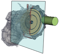
- Opacity
Specifies the cutting plane opacity, between 0 (transparent) and 255 (opaque). When the opacity is less than 8, only a ruler can move the actor. To select the cutting plane, use the Collaboration pane.
 |
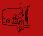 |
| Opacity = 0 |
Opacity = 255 |
|
- Color
Specifies the cutting plane color.
 |
 |
| Green |
Yellow |
|
- Axis
Specifies the cutting plane axis:
X,
Y,
Z,
X-,
Y-,
Z-, or
User.
 |
 |
| X-axis |
Y-axis |
 |
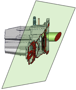 |
| Z-axis |
User-defined |
|
- Depth
Specifies the depth of the cutting plane. You can also change depth by dragging cutting planes in the viewport.
|
- Offset
Specifies the depth value.
|
- Auto flip
Flips (inverses the cutting plane normal) automatically as you rotate the model.
|
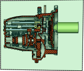
- Front/Back space opacity
Specifies the opacity (transparent = 0, opaque = 255) of the portion of the model in front of the cutting plane and the portion behind the cutting plane.
 |
| Front space opacity = 30
Back space opacity = 255 |
Note:
These properties are available for a cutting plane when at most one cutting plane is visible. When 2 or more cutting planes are visible, select the
Cutting planes
 parent node in the Collaboration pane and set
Front space opacity and
Back space opacity as needed. parent node in the Collaboration pane and set
Front space opacity and
Back space opacity as needed.
|
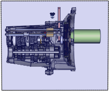
| Cutting line |
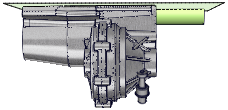
- Show
Displays the cutting line.
 |
 |
| Disabled |
Enabled
Color=Red |
|
- Thickness
- Specifies the width, in millimeters, of the cutting line and hatch lines.
Note:
In vector output, the width of cutting lines due to capping is computed by:
(actor property) x
Silhouette width (Technical Illustration - Lines) x
Global line width(Technical Illustration - Lines). Cutting-line
Thickness is ignored.
|
- Color
- Specifies the color of the cutting line and hatch lines.
Note:
You cannot override hatch-line color from the Technical Illustration workshop. To create vector output with black hatch lines, set
Color to black.
|
- Cut invisible actors
- (Available when
Show is enabled.) Displays the cutting line where the cutting plane intersects actors with
Opacity = 0. To disable the cutting line for invisible actors, clear this property.
|
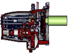
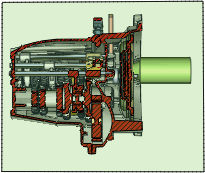
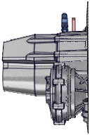
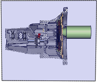
| Capping |
- Show
Creates surfaces where the cutting plane intersects solid model geometry.
 |
 |
| Disabled |
Enabled |
|
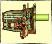
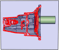
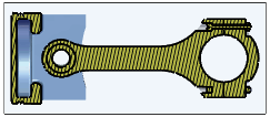
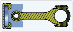
- Keep actor color
Caps surfaces using actor colors instead of the same color for all actors (as specified by
Color).
Notes:
- This property requires an OpenGL extension. Ensure the
HardwareSupport.Advanced setting (Application Preferences - Advanced Settings) is enabled. If this property is unavailable, your video card does not support this extension.
-
Hatch and
Keep actor color are not compatible. It is recommended that you select
Lighted capping with
Keep actor color
, especially for merged cutting planes.

|

|
| Disabled
Color=Red |
Enabled |
|
- Lighted capping
- (Available when
Keep actor color is selected.) Specifies that capping is affected by scene lighting.
|
- Color
- (Available when
Keep actor color is cleared.) Specifies the capping color.
Note:
You cannot override capping color from the Technical Illustration workshop. To create vector output without capping color, set
Color to white.
|
| Hatching
(Available when
Capping is enabled)
|
- Angle
- Specifies the rotation angle of hatch lines.
|
- Hatch
- (Available when
Hatch by actor is cleared.)
Specifies the spacing between hatch lines. To turn off hatching, specify 0.
Notes:
- When
Hatch by actor is selected, set hatch spacing for each actor using the actor's
Hatch property.
- When
Hatch by actor is cleared, set hatch line width and color using the
Cutting line properties
Thickness and
Color.
- Hatch lines in vector output do not necessarily match what is displayed in the viewport. Vectorization creates hatch lines in 2D space whereas the viewport shows 3D space.
|
- Hatch by actor
Enables different hatch spacing and angles for each geometry actor. After selecting this property, use
Initialize spacing and
Initialize angles to generate per-actor hatching and then optionally modify actor-specific
Hatching properties. To have uniform hatching across the entire cutting plane, clear this property.
Notes:
- This property requires an OpenGL extension. Ensure the
HardwareSupport.Advanced setting (Application Preferences - Advanced Settings) is enabled. If this property is unavailable, your video card does not support this extension.
- Hatching for each actor is computed separately, which can affect performance.
- Each actor has one set of hatching properties that apply to all cutting planes (with
Hatch by actor selected) that intersect it.
|
|
| Disabled |
Enabled |
|
- Initialize spacing
- (Available when
Hatch by actor is selected.) Sets random per-actor hatch spacing. Click
Proceed to initialize hatch spacing and then change spacing as needed using the
Hatch property for each actor.
|
- Initialize angles
- (Available when
Hatch by actor is selected.) Sets random per-actor hatch angles. Drag the slider to initialize hatch angles and then
change angles as needed using the
Angle property for each actor.
Notes:
- Actors of the same size are assigned the same angle.
- Each slider position assigns different random hatch angles, but the assignments are always the same for a given position.
- Both the cutting plane and actor
Angle properties affect hatch angles.
|