Interface description
SOLIDWORKS Electrical Schematic
SOLIDWORKS Electrical Schematic
software provides you with all the tools required to create electrical
schematics. The interfaces are both modern and intuitive, ensuring that
you can easily access the features required for your design.

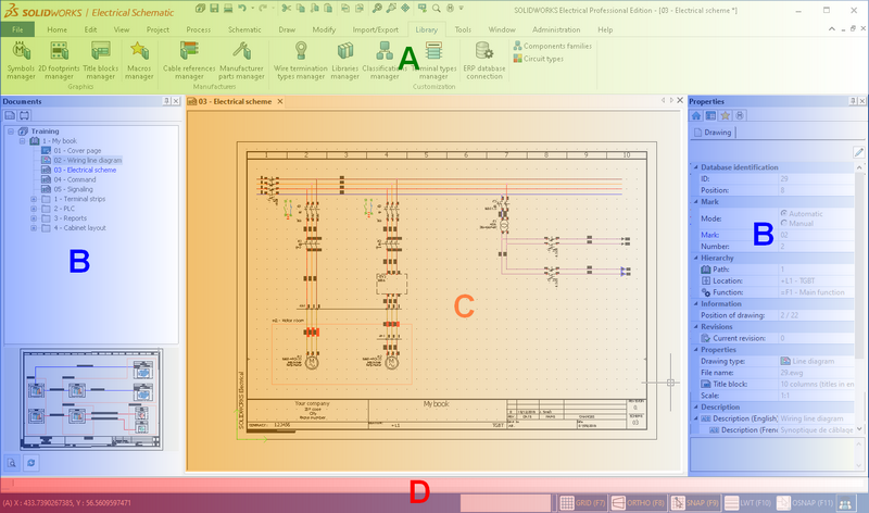
A . Ribbons
The menu zone, or Ribbons, groups
commands that allow you to realize your design. The commands are grouped
by ribbon and you can access the appropriate ribbon simply by selecting
the tab header. This opens the ribbon and displays all its commands. The
available ribbons vary depending on the drawing type you have Current
in the graphics area. For example, if you are working on a schematic drawing,
then a Schematic ribbon tab will
be available; in a Single Line Diagram, a Line
Diagram ribbon tab will be available. Some ribbon commands have
drop-down menus; clicking one of these icons will cause the drop-down
commands to be shown.
You can collapse or expand the Ribbon
menu by clicking the following icons:


There is also a Quick access toolbar
that you can customize.
B . Dockable panels
The dockable panels contain several
specific tabs. They can be placed on the right or the left of the screen.
The tabs can be moved from a dockable panel to the other by using drag
and drop. The View menu (Dockable panels section) allows
you to manage these tabs.
C . Graphical area
The graphical area displays the schematic drawings that comprise the
electrical project (you can open multiple drawings simultaneously). The
drawing that is displayed is known as the Current
Drawing. All drawings are automatically saved when they are closed
or when you open another one. You can switch between active drawings by
selecting the tab that displays the drawing name you want to make current.
The tooltip on the drawing tab indicates the
complete path of the drawing.
D . Status Bar
It contains information relating to the status of the drawing in the
graphical area. This includes the cursor coordinates and makes it possible
to manage the drawing parameters. Clicking
a parameter (such as Ortho, Grid, or Snap)
in the status bar or using the keyboard shortcuts allows you to turn it
on or off.
GRID: Shows or hides the grid
in the drawing.
ORTHO: Turn the ortho trap on
or off; this fixes cursor movement on either an X or Y axis.
SNAP: Turns the snaps on or
off. The snaps make your cursor snap to the preferred location and
should not be confused with the grid settings.
LWT: Turn the line weight on
or off; this shows or hides the various line thicknesses.
OSNAP: Turns the OSNAP
on or off. Right-clicking on the snap allows you to access and change
the various OSNAP settings.
SOLIDWORKS Electrical 3D
This interface is displayed when you
are working on designs in the SOLIDWORKS
software. SOLIDWORKS Electrical
allows you to create your assembly layout; the wiring module will automatically
carry out the assembly cabling.

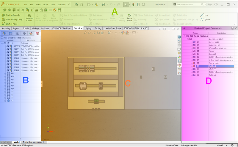
A . Menu Zone
The menu zone
groups together the SOLIDWORKS Electrical
commands.
The SOLIDWORKS Electrical
commands are available in the Ribbon
menu in the toolbar and in the drop-down menu.
B . Component Explorer
This is displayed when the SOLIDWORKS Electrical
tab is active. It lists the components by the location in which they are
placed. Checkboxes beside the components allow you to see which ones have
been inserted into the graphics area.
C . Graphical area
The SOLIDWORKS
graphical area lets you insert your components while allowing access to
the SOLIDWORKS
commands in the graphical area.
D . Page Navigator
The Page
navigator is displayed when the SOLIDWORKS Electrical
tab is active. It lists electrical projects as well as the drawings and
documents contained within them. Double-clicking an item (or right-clicking
and selecting Open from the contextual
menu) opens it. Only SOLIDWORKS
documents can be opened in the graphical area.
Keyboard shortcuts
Ctrl + W: Closes the current file.
Ctrl + P: Prints the current file.
Ctrl + N: Creates a new DWG file.
Ctrl + O: Opens an existing DWG (or
DXF) file
Ctrl + Shift + S: Saves the current
file as.
Ctrl + S: Saves the current file.
Ctrl + E: Zoom in on the whole graphic.
Ctrl + F: Search in the electrical
project.
Ctrl + K: Hyperlink.
Ctrl + Q: Exits the software.
Ctrl + X: Cut.
Ctrl + C: Copy.
Ctrl + Shift + C: Copy with insertion
point.
Ctrl + V: Paste.
Ctrl + Shift + V: Paste special.
Del: Deletes the selected object.