Mesh quality plays a key role in the accuracy of the results. SOLIDWORKS
Simulation uses the following parameters to measure the quality of elements in a
mesh.
Aspect Ratio
For a solid mesh, you achieve the best numerical accuracy with a mesh
that has uniform perfect tetrahedral elements whose edges are equal in length. For a
general geometry, you cannot create a mesh of perfect tetrahedral elements.
Because of small edges, curved geometry, thin features, and sharp
corners, some of the generated elements can have much longer edges than others. When
the edges of an element differ in length substantially, the results are less
accurate.
The aspect ratio of a perfect tetrahedral element is used as the
basis for calculating aspect ratios of other elements. The aspect ratio of an
element is the ratio between the longest edge and the shortest normal dropped from a
vertex to the opposite face, normalized with respect to a perfect tetrahedral.
By definition, the aspect ratio of a perfect tetrahedral element is
1.0. The aspect ratio check assumes straight edges connecting the four corner nodes.
The software calculates the aspect ratio to check the mesh quality.
Example
 |
 |
| Element with aspect ratio
close to 1.0 |
Element with large aspect
ratio |
A good-quality mesh has an Aspect ratio less than 5 for most of its
elements (90% and above). Create a Mesh Quality Plot to plot the Aspect ratio of all
elements.
Jacobian Ratio
Available for second order mesh elements (high quality solid and
shell mesh).
The Jacobian ratio measures the deviation of an element’s shape from
an ideally shaped element (one that has straight edges with equal lengths). The
Jacobian ratio of a perfect second order tetrahedral element with linear edges is
1.0. The Jacobian ratio of an element increases as the curvature of the element
edges increases to map a curved geometry.
Near extremely sharp or curved boundaries, the edges of an element
can cross over each other and the element becomes distorted, resulting in
self-intersecting geometry. Distorted elements have a negative Jacobian ratio and
produce inaccurate results.
In the Mesh PropertyManager, the
Issue warning for distorted elements
option alerts you if there are distorted elements in the mesh. To remove distorted
elements, first check the model for any geometry irregularities. Refine the mesh in
areas where distorted elements exist.
The Jacobian ratio check considers the Gaussian points located within
each element. The default value in a new study is 16 Gaussian points.
Recommendation: Set Jacobian
check to At Nodes when using
the p-method to solve static problems.
For high-order shells, the Jacobian
check uses 6 points located at the nodes.
A good quality mesh has a Jacobian ratio between 1 and 10 for the
majority of its elements (90% and above). Create a Mesh Quality Plot to plot the
Jacobian ratio of all elements.
For most models, elements at regions of high curvatures have higher
Aspect and Jacobian ratios. If the elements with the highest Aspect and Jacobian
ratios (larger than 10) are away from critical areas for the analysis, it might not
be worthwhile to refine the mesh in these areas. However, for areas that are
critical for the simulation, you can refine the mesh locally to reduce the Aspect
and Jacobian ratios for the poor quality elements and improve the simulation
results.
Depending on the geometry of the model, subsequent levels of mesh
refinement might not improve further the mesh quality and the simulation results.
After each level of mesh refinement, confirm that the mesh quality plots for Aspect
ratio and Jacobian ratio show fewer poor-quality elements. In addition, ensure that
after each successful mesh refinement, the simulation results converge to finite
values.
Element Area
(Available only for shell mesh).
The Element area check measures the surface area of each element
against a limit surface area value. The mesh algorithm identifies elements with
surface areas less than the limit value as poor-quality elements and removes these
elements from the mesh. The table lists the accepted limit values of an element's
surface area for each mesher.
| Mesher |
Limit of Element
Area |
| Standard |
(Mesh element tolerance) ^2 *
0.001 |
| Curvature-based |
(Minimum element size) ^2 *
0.001 |
| Blended
Curvature-based |
(Minimum element size) ^2 *
0.001 |
To view a Mesh Quality Diagnostics plot based on
the Element area:
In the Mesh Quality
Diagnostics PropertyManager, under Display, select Element
area.
Skewness
(Available only for shell mesh.)
Skewness is the angular measure of an element’s quality with respect
to the angles of an ideal element type. For a triangular element, the skewness is
the ratio of the angular deviation from an element that has an ideal shape.
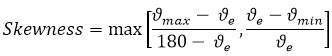
 = largest angle
of element face
= largest angle
of element face
 = smallest angle
of element face
= smallest angle
of element face
 = angle of an
equiangular element (equals 60° for an equilateral triangle and 90° for a
square)
= angle of an
equiangular element (equals 60° for an equilateral triangle and 90° for a
square)
A perfect equiangular triangle has a skewness value of 0. SOLIDWORKS
Simulation identifies elements that have skewness values greater than 0.9 as
poor-quality elements. You can specify a skewness value as less than 0.9 to apply a
stricter criterion.
To view a Mesh Quality Diagnostics plot based on
the Skewness:
In the Mesh Quality
Diagnostics PropertyManager, under Display, select Skewness.