 | Detect Clones | Detects parts that have identical or similar geometry and creates instances (when they are not already instances imported from CAD). For details, see Clones Detection Tab. |
 | Merge Geometry | Merges all geometry of the selected actors into a new actor.
New (merged) actors appear under the lowest common parent in the assembly tree. When there is no selection, the entire scene is merged under the assembly root. Merging reduces the number of actors, which improves performance (animation speed, load and save time).
|
 | Merge Geometry by Color | Same as
Merge Geometry except merges only geometry of the same color.
|
 | Keep Animation When Merging Mode
| Preserves animations when merging. Composer merges only actors with the same keys (on the actors and their parent assemblies). When this option is cleared, Composer merges actors without considering keys, which can break animations. |
 | Explode Geometry
| Exposes faces for the selected geometry actors. For example, explode a part to apply different face colors or textures.
 | 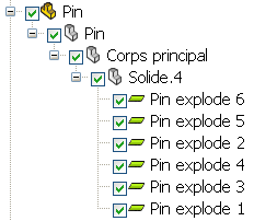 | | Before | After |
|
 | Explode Geometry by Color | Explodes geometry by color. |
 | Update Geometry | Updates selected actors from a CAD file. This command updates changes in geometry, adds new actors, and deletes old actors. It does not update meta-properties or change the relative positions of actors. Association between actors in the active document and the file is by actor ID, which is based on actor name. You cannot update geometry if IDs have changed.
If only one actor is selected and there is one actor in the file with a different name, you are prompted before updating the geometry. If a part has instances, all instances are updated (because they share the same reference). You cannot replace just one instance.
|
 | Copy Geometry
| Copies the geometry and properties of selected actors and creates new instances (clones). The clones are named
copy of
actor_name and appear in the Assembly tree under the same parents as the copied actors. To create clones under a different parent, use the
Copy Actors and
Paste Actors right-click commands in the assembly tree.
See Right-click Commands. 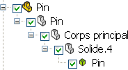 | 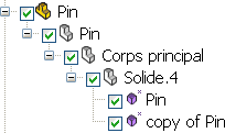 | | Before | After |
|
 | Replace Geometry
| Replaces the geometry (mesh) of the selected actors with the geometry of another actor in the model. For example, you can substitute a screw in your model with a replacement screw. All properties of the replaced actors are unchangedexcept
Emission and
Shininess, which take the replacement actor's values. All views and animations are preserved.
To replace geometry, select one or more actors to replace, click this command, and then select the replacement actor. |
 | Scale Geometry
| Scales the selected geometry actors in the world coordinate system. See the
Scale Geometry dialog box.
|
 | Symmetrize Geometry
| Makes the geometry symmetrical according to the desired point, plane, or axis. To duplicate the geometry, copy it first. |
 | Flip Faces | Changes the direction of badly directed faces, which can affect actor rendering. |
 | Flip Normals | Changes the direction of the normals, which can affect actor rendering. |
| Primitives | Creates simple geometry actors:
-
Point
-
Line
-
Square (To create a rectangle, modify
Width or
Depth in the Properties pane)
-
Disc
-
Cube
-
Sphere
-
Cylinder
For example, use primitives to embellish your scene, such as creating floors and walls. You can change properties and apply meta-properties to primitives from the Properties pane. |
 | Secure 3D Brush | Protects your intellectual property (IP) by degrading information at the geometrical level while preserving total model coherence. For details, see the
Secure 3D Brush dialog box. |