You can specify the surface texture of a part face by using a surface finish symbol. You can select the face in a part, assembly, or drawing document.
Surface finish symbols are formed by combining the Symbol and Lay Direction (direction of lay).
For ISO and related drafting standards, you can display surface finish symbols per 2002 standards by selecting Display symbols per 2002 in .
Examples:
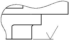
Basic symbol with None as direction of lay:

|
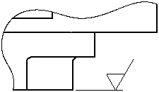
Machining Required symbol with None as direction of lay:

|
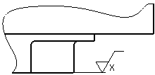
Machining Required symbol with Crossed direction of lay:

|
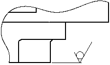
Machining Prohibited symbol with None as direction of lay:

|