Rotate View

Rotates the model view in part and assembly documents.

To rotate the model view:

Do one of the following:
Device Procedure
Mouse (left button) Click Rotate View (View toolbar) or View > Modify > Rotate then drag the pointer .
Mouse (middle button) Drag with the middle mouse button.
Keyboard Press the arrow keys. Hold down Shift to rotate in 90° increments.
To change options such as mouse speed and arrow key angle increments, see View Options.

To change settings for transparency quality used during rotation, see Performance Options.

Rotating About a Vertex, Edge, or Face

To rotate about a vertex, edge, or face:

Do one of the following:
Device Procedure
mouse (left button) Click Rotate View or View > Modify > Rotate; select a vertex, edge, or face; then drag the pointer.
mouse (middle button) Middle-click a vertex, edge, or face; then middle-drag the pointer.

Rotating About the Scene Floor

You can lock the vertical axis in relation to the front view during view rotation. This prevents the model from tipping and tilting about the horizon plane and creates the impression that the model is on a floor.

Right-click in the graphics area and click Rotate about scene floor.

The vertical axis locks in relationship to the front view. If your model's front view does not match the vertical axis you want to rotate around, you can change the front view. Navigate to the view you want to be the front view and click View > Modify > Set Current View As > Front.

For example, this image shows the front view of the tractor.
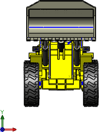
front_view_toy_truck.gif
The vertical axis of rotation locks around the Y axis and the floor is parallel to the X axis. In the following image, the dotted red arrow indicates the locked axis of rotation:
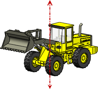
toy_truck_vertical_axis.gif
The Y axis is the vertical axis by default. However, if you update standard views, the vertical axis might change