In this exercise, you
learn how to manage the PLCs.
PLC Management
Add thisPLC:
- Brand: Schneider Electric
Part:
TWDLCDA16DRF
Nine Digital inputs + Seven Digital
outputs
- Click
 .
.
- Click .
- Allocate the requested part.

Input/Output Management
- Create the following:
- Nine digital inputs with Sensor #1 to Sensor #9
designations
- Seven digital outputs with Solenoid #101 to Solenoid
#107 designations
- Do one of the following:
- Click
 .
.
- Click
 .
.
- Click .
- Add the nine digital inputs and seven digital outputs that you
created.
- Select the channel and click Properties to add a description.
You can
also select the channel by clicking Description.
Next, save the digital inputs in a macro.
- Select the inputs to create the PLC macro.
- In Input/Output
management, select the User
I/O group.
- Click to add the macro to the group you created.
Next, associate this I/O with the N1 PLC channels.
- In PLC management,
select the nine Digital PLC inputs
and click Associate I/O.
- In PLC management,
select the nine Digital PLC inputs
and click Select.
- Repeat steps 1 and 2 for the seven Digital PLC outputs.
Next, insert a page break between the inputs and outputs.
- Click
 .
.
- Right-click the last Digital
PLC input and select Add/Remove
a page break.

Editing the Macro Associated with a Circuit
In the PLC board drawing configuration, the circuits are associated with a
macro. Edit the macro associated with the digital input to replace the pressure
sensor symbol with a thermal sensor symbol.
- Do one of the following to open the PLC drawing configuration:
- Click .
- In the panel, right-click an electrical project and
select .
- In the
Configuration
dialog box, open the properties of the configuration.
- In PLC drawing
configuration, under Circuits, for Circuit
type, select Digital PLC
input.
The module is drawn in the upper
part of the drawing.
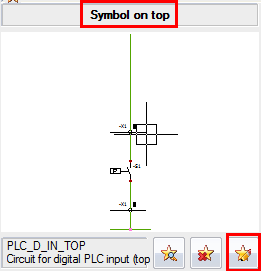
- Under Symbol on
top, click Macro
modification.

The macro is
added to the Pages tab of the
panel and opens in the graphics area.
- Right-click a symbol, select and select a pressure sensor symbol.
- Close the macro.
The configuration
automatically updates.
Generating PLC Drawings
You can generate PLC drawings and redirect them to a folder titled
PLCs and open the drawings to complete
them according to Appendix 8.
- Click
 .
.
- In PLCs manager,
click Generate drawings
 .
.
- In the Selection of: Books,
Folder dialog box, click New
folder and create the PLCs folder.
- Select the folder.
The drawings are
generated automatically.
